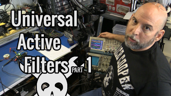
Today I am experimenting with a single chip Universal Active Filter, in this case I made a small PCB for the UAF-42 from Texas Instruments. I chose this part in particular as it facilitates setting the filter frequency by changing just a pair of resistors and the somewhat critical values that are contained on the chip have been laser trimmed for accuracy. This type of active filter includes Operational Amplifiers to supply gain and it supports various configurations including simultaneous operating modes such as Band Pass, Low Pass and High Pass make it “Universal”.


Filter Basics
Looking at the block diagram you can see where I have inserted a dual-ganged potentiometer to change both resistors simultaneously which should allow a straight forward adjustment for our purposes here.
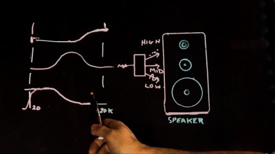
Looking into the components of a simple RC filter which can easily implement a simple Low Pass or High Pass filter, we see that the math is fairly straight forward and swapping the components with each other is all that is needed to change the type of filter. Continue reading “Universal Active Filters: Part 1”
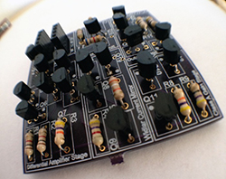 By now we’ve all seen the ‘Three Fives’ kit from Evil Mad Scientist, a very large clone of the 555 timer built from individual transistors and resistors. You can do a lot more in the analog world with discrete parts, and