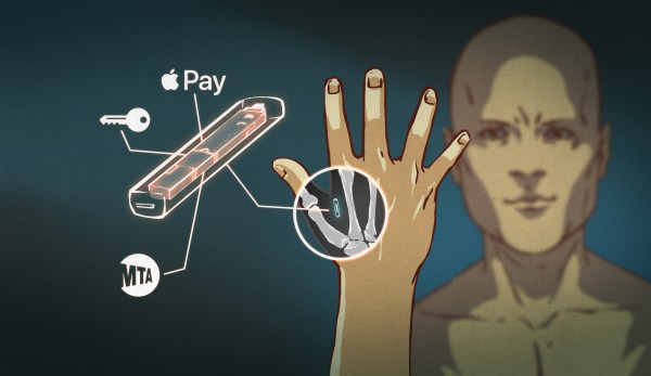
Ask Hackaday: Helping Hands

[ProtoG] sent us in this video (also below) where he demonstrates the use of machinist’s dial-gauge indicator arms as helping hands. I’ll admit that I got so jealous that I ordered a pair. I wouldn’t say that I need more tools to hold things in place, but I certainly want them. The rapid coarse placement combined with fine adjustment looks so sweet. Using them as scope-probe holders is brilliant.

Our own helping hands, purchased for $5 from a surplus shop, have seen nearly twenty years of use now. About ten years ago, I heat-shrinked and plasti-dipped the jaws, and since then they do less damage to cable insulation. The clips kept coming loose, but that was fixed with a little epoxy. I never used the magnifying glass, and by removing it I bought some more sliding room for the jaws, which was an easy win. The base has a “non-slip” coating of Shoe-Goo that keeps it in place on the desk. Cork might be classier.

For bigger holding, there’s always the desk vise, though I’ll admit that I mostly use it for holding PCBs while soldering, and that a better solution for that particular task wouldn’t hurt. [Mike Szczys] tells me that the Stickvise seen here is a handy thing to have on the bench. It started on Hackaday.io and we still carry it in the store.

For grabbing the fiddly little things, nothing beats a pair of hemostats and a range of tweezers. Hemostats in the desk vise make a great ad hoc holder. Good sharp tweezers pay for themselves with the first removed splinter, or placing SMT parts.

So, Hackaday, what do you use for holding things? What do you hold your PCBs with while soldering? What do you use to hold down SMD parts? What’s your third hand, or twenty-third? Continue reading “Ask Hackaday: Helping Hands”

Ask Hackaday: Bitten By The Crocodile Clip

I have a love/hate relationship with the crocodile clip. Nothing is so quick to lash together a few half-baked prototype boards on your desk, but nothing ends up in such a tangle so quickly, either. I love the range of pretty colors that crocodiles come in, as well as the easy ability to just clip on to the side of a PCB, or any old loose wire. But they come loose, they can have intermittent contacts, and we’re not even sure if there is such a thing as a current rating for them.

When [WarriorRocker] wrote in asking what we use instead of crocodile clips, he included a photo that sent a chill down my spine, from a review of some clips on Amazon. I’ve seen this one in real life. And what’s worse is the one with the loose wires that sometimes make contact with the spring-clip body and sometimes not.

After an hour-long debugging session about twelve years ago now, such an intermittent croc caused us to make a lifelong vow. All of our croco-clips have been disassembled, manually inspected, and many of them soldered together. When I buy new ones, I check them all before mixing them in with the known-goods. Even thinking about this now makes me want to pull back their little rubber booties just to make sure. Continue reading “Ask Hackaday: Bitten By The Crocodile Clip”

Ask Hackaday: Dude, Where’s My MOSFET?

(Bipolar Junction) Transistors versus MOSFETs: both have their obvious niches. FETs are great for relatively high power applications because they have such a low on-resistance, but transistors are often easier to drive from low voltage microcontrollers because all they require is a current. It’s uncanny, though, how often we find ourselves in the middle between these extremes. What we’d really love is a part that has the virtues of both.

The ask in today’s Ask Hackaday is for your favorite part that fills a particular gap: a MOSFET device that’s able to move a handful of amps of low-voltage current without losing too much to heat, that is still drivable from a 3.3 V microcontroller, with bonus points for PWM ability at a frequency above human hearing. Imagine driving a moderately robust small DC robot motor forwards with a microcontroller, all running on a LiPo — a simple application that doesn’t need a full motor driver IC, but requires a high-efficiency, moderate current, and low-voltage-logic compatible transistor. If you’ve been here and done that, what did you use?

Continue reading “Ask Hackaday: Dude, Where’s My MOSFET?”

Ask Hackaday: What’s Your Favorite Internet Relic?

[Sadiq Mohamed] posted this great list of light bulb jokes in our post about drones changing light bulbs. This favored relic used to exist on a Compuserve SIG, but fortunately a dedicated user had saved the list.

There have been virtual worlds long before our computers could render anything but potatoes with anime faces. Bulletin boards, mailing lists, and forums dominated and then fell, for the most part, to social media. In a way even the personal home page has gone to the wayside. (remember geocities?)

The internet has gone through many phases of development. We’ve experimented with lots of concepts and when they fail or go out of style, there are ghost towns of information left untouched.

However, we remember. I still think fondly of my old shell server. Some of it is even history worthy enough to be in the books. What’s your favorite piece of internet gone by or just plain internet obscura? An old joke? A book five layers deep in a file structure somewhere. Or maybe just the 1959 definition of the word, “hack,” in the Tech Model Railroad Club’s first edition dictionary.

Ask Hackaday: How Do You Make A Hotplate?

Greetings fellow nerds. The Internet’s favorite artificial baritone chemist has a problem. His hotplates burn up too fast. He needs your help to fix this problem.

[NurdRage] is famous around these parts for his very in-depth explorations of chemistry including the best ways to etch a PCB, building a thermometer probe with no instructions, and chemical synthesis that shouldn’t be performed by anyone without years of experience in a lab. Over the past few years, he’s had a problem: hotplates suck. The heating element is usually poorly constructed, and right now he has two broken hotplates on his bench. These things aren’t cheap, either: a bare-bones hotplate with a magnetic stirrer runs about $600.

Now, [NurdRage] is asking for help. He’s contacted a few manufacturers in China to get a hundred or so of these hotplate heating elements made. Right now, the cost for a mica and metal foil hotplate is about $30 / piece, with a minimum order quantity of 100. That’s $3,000 that could be better spent on something a bit more interesting than a heating element, and this is where you come in: how do you build the heating element for a hotplate, and do it cheaply?

If you buy a hotplate from the usual lab equipment supplier, you’ll get a few pieces of mica and a thin trace of metal foil. Eventually, the metal foil will oxidize, and the entire hotplate will stop working. Repairs can be done with copper tape, but by the time that repair is needed, the heating element is already on its way out.

The requirements for this heating element include a maximum temperature of around 350 ºC. That’s a fair bit hotter than any PCB-based heat bed from a 3D printer gets, so consider that line of reasoning a dead end. This temperature is also above what most resins, thermoplastics, and composites can handle, which is why these hotplates use mica as an insulator.

Right now, [NurdRage] will probably end up spending $3,000 for a group buy of these heating elements. That’s really not that bad – for the price of five hotplates, he’ll have enough heating elements to last through the rest of his YouTube career. There must be a better way, though, so if you have an idea of how to make a high-temperature heating element the DIY way, leave a note in the comments.

Ask Hackaday: Is The ESP8266 5V Tolerant?

The ESP8266 is the reigning WiFi wonderchip, quickly securing its reputation as the go-to platform for an entire ecosystem of wireless devices. There’s nothing that beats the ESP8266 on a capability vs. price comparison, and this tiny chip is even finding its way into commercial products. It’s also a fantastic device for the hardware tinkerer, leading to thousands of homebrew projects revolving around this tiny magical device.

In every technical document, summary, and description of the ESP8266, the ESP8266 is said to be a 3.3V part. While we’re well into the age of 3.3V logic, there are still an incredible number of boards and hardware that still operate using 5V logic. Over on the Hackaday.io stack, [Radomir] is questioning this basic assumption. He’s wondering if the ESP8266 is 5V tolerant after all. If it is, great. We don’t need level converters, and interfacing the ESP to USB TTL serial adapters becomes much easier. Yes, you’ll still need to use a regulator if the rest of your project is running at 5V, but if the pins are 5V tolerant, interfacing the ESP8266 with a variety of hardware becomes very easy.

[Radomir]’s evidence for the possibility of 5V tolerant inputs comes from a slight difference in the official datasheet from Espressif, and the datasheet translated by the community before Espressif realized how many of these chips they were going to sell.

The best evidence of 5V tolerant pins might come from real-world experience — if you can drive a pin with 5V for months on end without it failing, there might be something to this claim. It’s not definitive, though; just because a device will work with 5V input pins for a few months doesn’t mean it won’t fail in the future. So far a few people have spoken up and presented ESPs directly connected to the 5V pin of an Arduino that still work after months of service. If this is evidence of 5V tolerant design or simply luck is another matter entirely.

While the official datasheet from Espressif lists a maximum VIH of 3.3V, maximum specs rarely are true maximums — you can always push a part harder without things flying apart at the seams. Unfortunately, unless we hear something from the engineers at Espressif, we won’t know if the ESP8266 was designed to be 5V tolerant, if it can handle 5V signals reliably, or if 5V signals are a really good way to kill a chip eventually.

Lucky for us — and this brings us to the entire point of an Ask Hackaday column — a few Espressif engineers read Hackaday. They’re welcome to pseudonymously chime in below along with the rest of the peanut gallery. Failing that, the ESP8266 has been decapped; are there any die inspection wizards who can back up a claim of 5V tolerance for the GPIO? We’d also be interested in hearing any ideas for stress testing pin tolerance.

Ask Hackaday: How Hard Is It To Make A Bad Solder Joint?

When you learn to solder, you are warned about the pitfalls of creating a solder joint. Too much solder, too little solder, cold joints, dry joints, failing to “wet” the joint properly, a plethora of terms are explained  if you read one of the many online guides to soldering.

Unsurprisingly it can all seem rather daunting to a novice, especially if they are not used to the dexterity required to manipulate a tool on a very small-scale at a distance. And since the soldering iron likely to be in the hands of a beginner will not be one of the more accomplished models with fine temperature control and a good tip, it’s likely that they will experience most of those pitfalls early on in their soldering career.

As your soldering skills increase, you get the knack of making a good joint. Applying just the right amount of heat and supplying just enough solder becomes second nature, and though you still mess up from time to time you learn to spot your errors and how to rework and fix them. Your progression through the art becomes a series of plateaux, as you achieve each new task whose tiny size or complexity you previously thought rendered it impossible. Did you too recoil in horror before your first 0.1″ DIP IC, only to find it had been surprisingly easy once you’d completed it?

A few weeks ago we posted a Hackaday Fail of the Week, revolving around a soldering iron failure and confirmation bias leading to a lengthy reworking session when the real culprit was a missing set of jumpers. Mildly embarrassing and something over which a veil is best drawn, but its comments raised some interesting questions about bad solder joints. In the FoTW case I was worried I’d overheated the joints causing them to go bad, evaporating the flux and oxidising the solder. This was disputed by some commenters, but left me with some curiosity over bad solder joints. We all know roughly how solder joints go wrong, but how much of what we know is heresay? Perhaps it is time for a thorough investigation of what makes a good solder joint, and the best way to understand that would surely be to look at what makes a bad one.

Continue reading “Ask Hackaday: How Hard Is It To Make A Bad Solder Joint?”