Gigantic FPGA In A Game Boy Form Factor, 2019 Supercon Badge Is A Hardware Siren Song

Look upon this conference badge and kiss your free time goodbye. The 2019 Hackaday Superconference badge is an ECP5 FPGA running a RISC-V core in a Game Boy form factor complete with cartridge slot that is more open than anything we’ve ever seen before: multiple open-source CPU designs were embedded in an open system, developed using the cutting-edge in open-source FPGA tools, and running (naturally) open-source software on top. It’s a 3,000-in-one activity kit for hardware people, software people, and everyone in between.

The brainchild of Jeroen Domburg (aka Sprite_TM), this design has been in the works since the beginning of this year. For more than 500 people headed to Supercon next week, this is a source of both geeky entertainment and learning for three action-packed days and well beyond. Let’s take a look at what’s on the badge, what you need to know to hack it, and how the design serves as a powerful development tool long after the badge hacking ceremonies have wrapped up.

Continue reading “Gigantic FPGA In A Game Boy Form Factor, 2019 Supercon Badge Is A Hardware Siren Song”

Saintcon Badge Is An Enigma No More

Through the weekend Twitter has been a-titter with news coming out of Saintcon, the annual security conference in Provo, Utah. Now that the weekend is over we can finally get our hands on full hardware and software sources for the curvy, LED-covered badge we’ve been salivating over and a write up by its creators [compukidmike] and [bashNinja]. Let’s dive in and see what’s waiting!

Design

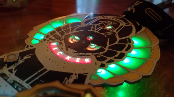
This year’s badge is designed to represent a single tooth on a single rotor of an Enigma machine. The full function of an Enigma machine is quite complex, but an individual device has three rotors with 26 teeth each (one for each letter) as well as a keypad for input and a character display to show each enciphered letter. For reference, the back of the badge has a handy diagram of a badge’s place in the Enigma system.

Reminiscent of the WWII device which the badge design recalls, each unit includes a full QWERTZ keyboard (with labeled keys!) and RGB “lampboard” for individual character output, but unlike the original there’s also a curved 16 x 64 RGB LED display made from those beguiling little ~1mm x 1mm LEDs. All in, the device includes 1051 LEDs! Combined with the unusually non-rectilinear shape of the badge and the Enigma-style Saintcon logo it makes for an attractive, cohesive look.

Continue reading “Saintcon Badge Is An Enigma No More”

Tiny Cube Hosts A Hearty Tube

Tiny PCBAs and glowy VFD tubes are like catnip to a Hackaday writer, so when we saw [hamster]’s TubeCube tube segment driver we had to dig in to learn more. We won’t bury the lede here; let’s enjoy a video of glowing tubes before we go further:

The TubeCube is built to fit the MiniBadge badge addon standard, which is primarily used to host modules on the SAINTCON conference badge. A single TubeCube hosts a VFD tube, hardware to provide a 70 V supply, and a microcontroller for communication and control. Each TubeCube is designed to accept ASCII characters via UART to display on it’s display, but they can also be chained together for even more excitement. We’re not sure how [hamster] would be able to physically wear the beast in the video above, but if he can find a way, they all work together. If you’re interested in seeing the dead simple UART communication scheme take a look at this file.

We think it’s also worth pointing about the high voltage supply. To the software or mechanically minded among us it’s easy to get trapped thinking about switching power supplies as a magical construct which can only be built using all-in-one control ICs. But [hamster]’s supply is a great reminder that a switching supply, even a high voltage one, isn’t as complex as all that. His design (which he says was cribbed from Adafruit’s lovely Ice Tube Clock) is essentially composed of the standard primitives. A big low voltage capacitor C1 to source the burst of energy which will be boosted, the necessary inductor/high voltage cap C2 which ends up at the target voltage, and a smoothing cap C3 to make the output a little nicer. It’s controlled by the microcontroller toggling Q1 to control the current flow through L1. The side effect is that by controlling the PWM frequency [hamster] can vary the brightness of the tubes.

Right now it looks like the repository has a schematic and sources, which should be enough to build a small tube driver of your own. If you can’t get enough TubeCubes, there’s one more video (of a single module) after the break.

Continue reading “Tiny Cube Hosts A Hearty Tube”

Hands-On: BornHack’s Light Sabre Badge

A badge modelled after the handle of a light sabre? Yes Please! This Star Wars themed hardware is the work of hardware designer Thomas Flummer for the 2019 BornHack conference held in Denmark last month. (Check out my roundup of the event if this is the first you’ve heard of it.)

It's not a badge but a light sabre! The front of the BornHack 2019 badge.
It’s not a badge but a light sabre! The front of the BornHack 2019 badge.

It fits the hand nicely, and with clever side-on placement of the two AA battery holders (a trick we first saw with the 2016 Hackday Superconference badge) it also keeps any protruding solder joints away from clothing. In the centre of the badge is the 240×240 pixel colour display that also hides the Silicon Labs Happy Gecko processor and its surrounding components. Three buttons at the edge of the board to the left of the screen are a nice fit for your thumb when holding it in your left hand — a good choice if you happen to leave your right hand behind on a visit to the Cloud City of Bespin.

Between the battery holders lies a four-way joystick, two buttons, and a 6-pin add-on connector. Above it is a micro SD card socket and a micro USB socket, and above them are an IR emitter and receiver. All of the hardware is on the front of the PCB, with no components on the reverse (other than the solder joints for the batteries). But it is there you will find a set of exposed pads for serial and I2C interfaces. Continue reading “Hands-On: BornHack’s Light Sabre Badge”

These Tips Make Assembling A Few Hundred PCBs Easier

There are a few common lessons that get repeated by anyone who takes on the task of assembling a few hundred PCBs, but there are also unique insights to be had. [DominoTree] shared his takeaways after making a couple hundred electronic badges for DEFCON 26 (that’s the one before the one that just wrapped up, if anyone’s keeping track.) [DominoTree] assembled over 200 Telephreak badges and by the end of it he had quite a list of improvements he wished he had made during the design phase.

Some tips are clearly sensible, such as adding proper debug and programming interfaces, or baking an efficient test cycle into the firmware. Others are not quite so obvious, for example “add a few holes to your board.” Holes can be useful in unexpected ways and cost essentially zero. Even if the board isn’t going to be mounted to anything, a few holes can provide a way to attach jigs or other hardware like test fixtures.

[DominoTree] ended up having to attach multiple jumper wires to reprogram boards after assembly, and assures us that “doing this a bunch of times really sucked.”
Other advice is more generic but no less important, as with “eliminate as many steps as possible.” Almost anything adds up to a significant chunk of time when repeated hundreds of times. To the basement hacker, something such as pre-cut and pre-tinned wires might seem like a shameful indulgence. But cutting, stripping, tinning, then hand-soldering a wire adds up to significant time and effort by iteration number four hundred (that’s two power wires per badge) even if one isn’t staring down a looming deadline.

[DominoTree] also followed up with additional advice on making assembly easier. Our own [Brian Benchoff] has also shared his observations on the experience of developing and assembling a large number of Hackaday Superconference badges, including what it took to keep things moving along when inevitable problems surfaced.

You don’t need to be making batches of hundreds for these lessons to pay off, so keep them in mind and practice them on your next project.

The Numberwang Badge Brought Cheer To CCCamp 2019

While wandering through CCCamp last weekend, in between episodes of forcing Marmite on the unwary, I ran into the well-known Hackaday.io user [Prof. Fartsparkle]. In a last-minute sprint leading up to the con he built himself the Numberwang badge to join in the colorful after-dark festivities with beautiful board artwork and remarkably enjoyable backlit LED display.

The Numberwang badge itself is a clone of the Adafruit Itsy Bitsy sporting an ATSAMD21G18 CPU and running CircuitPython. It has an LED strip on the reverse shining through the bare FR4 as a diffuser, and the Numberwang effect of selecting random numbers is achieved by a host of random touchable numbers sprinkled across its front. For something he freely admits was a last minute project, we think he’s done a pretty good job!

For those mystified by Numberwang, it is a fictional gameshow from a BBC TV comedy programme that involves contestants answering the quizmaster with random numbers. It joins a rich tradition of such hilarious nonsense, and has as a result become cult television.

If you’re really getting into Numberwang, don’t forget that it’s inspired a programming language.

Continue reading “The Numberwang Badge Brought Cheer To CCCamp 2019”

After The Con: Da Bomb Badge Post Mortem

We’ve reported on the world of electronic badges here at Hackaday since their earliest origins in [Joe Grand]’s work for DEF CON 14 in 2006. In that time we’ve seen an astonishing variety of creations, covering everything from abstract artwork to pure functionality in a wearable device. But it’s not been quite so often that we’ve looked at the other side of the BadgeLife coin, so it’s fascinating to read [John Adams]’ account of the work that went into the production of this year’s 500-piece run of the Da Bomb DEF CON indie badge.

In it, [John] goes over scheduling worries, component sourcing issues, PCB assembly delays, and an in-depth look into the finances of such a project. In case anyone is tempted to look at Badgelife as the route to millions, it rapidly becomes apparent that simply not losing too much money is sometimes the best that can be hoped for. There were a few design problems, one of them being that the SAO I2C bus was shared with the LED controller, resulting in some SAOs compatibility issues. In particular the AND!XOR DOOM SAO had its EEPROM erased, creating something of a headache for the team.

A surprise comes in the distribution: obviously shipping is expensive, so you’d think badge pick-ups at the con would be straightforward alternative. Unfortunately, they became something of a millstone in practice, and organising them was a Herculean task. Astoundingly, some paying customers didn’t bother turn up for their badges. Which was especially infuriating since the team lost valuable conference time waiting for them.

Some of you are BadgeLife creators and will nod sagely at this. Still more of you will wish you were BadgeLife creators and find it a useful primer. For everyone else it’s a fascinating read, and maybe makes us appreciate our badges a bit more.

The images may have departed, but just to return to the origins of BadgeLife, here’s our coverage of that first [Joe Grand] badge.