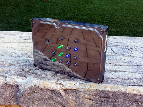
It’s about time we had another awesome clock post around here. [Mattaw] has liked binary clocks since he was 0 and decided to make one in stunning fashion by using driftwood, nature’s drillable, fillable enclosure.
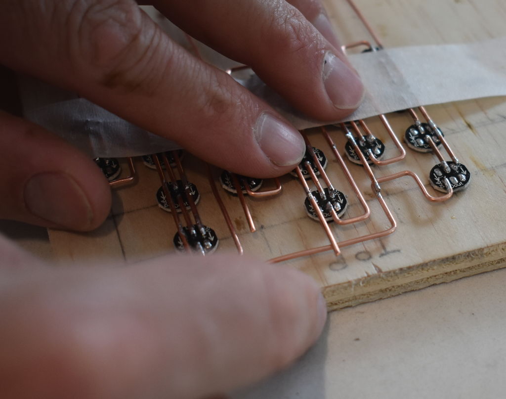 That beautiful wiring job on the RGB LEDs was done in 18g copper. To keep the LEDs aligned during soldering, he drilled a a grid of holes just deep enough to hold ’em face down. There’s an IR remote to set the time, the color, and choice of alarm file, which is currently set to modem_sound.mp3.
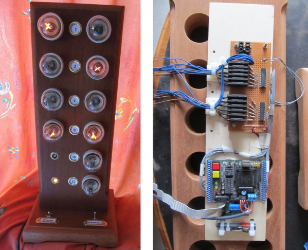
Under the wood, there are a pair of Arduino Nanos, an mp3 decoder board, and an RTC module. Why two Nanos, you ask? Well, the IR interrupts kept, uh, interrupting the LED timing. The remote feature was non-negotiable, so [mattaw] dedicated one Nano to receive remote commands, which it streams serially to the other. Here’s another nice touch: there’s an LDR in one of the nooks or crannies that monitors ambient light so the LEDs are never too bright. Don’t wait another second to check it out—we’ve got 10 videos of it after the break.
Believe it or not, this isn’t the first binary clock we’ve seen. This honey of a clock uses RGB LEDs to tell the time analog style.
Continue reading “Driftwood Binary Clock Is No Hollow Achievement”