Advertise Your Conference Schedule Via SSID

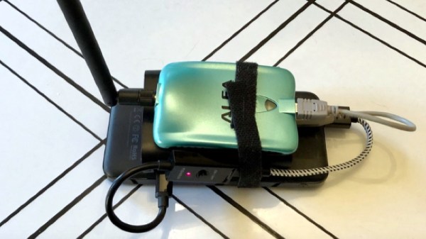
Whether it’s been a Python script running on a Linux box or an ESP8266, abusing using WiFi SSIDs to convey messages is hardly a new trick. But for DerbyCon 2019, [vgrsec] wanted to do put together something a little unique. Dare we say, even useful. Rather than broadcast out SSID obscenities or memes, this Raspberry Pi created fake WiFi networks that told everyone what talks were coming up.

The concept here is fairly simple: there’s a text file in /boot that contains the truncated names of all the talks and workshops in the schedule, one per line, and each line starts with the time that particular event is scheduled for. The script that [vgrsec] wrote opens this text file, searches for the lines beginning with the current time, and generates the appropriate SSIDs. With the number of tracks being run at DerbyCon, that meant there could be as many as five SSIDs generated at once.

Now in theory that would be enough to pull off this particular hack, but there’s a problem. The lack of an RTC on the Raspberry Pi means it can’t keep time very well, and the fact that the WiFi adapter would be busy pumping out SSIDs meant the chances of it being able to connect to the Internet and pull down the current time over NTP weren’t very good.

As the system was worthless without a reliable way of keeping time, [vgrsec] added an Adafruit PiRTC module to the mix. Once the time has been synchronized, the system could then run untethered via a USB battery bank. We might have put it into an enclosure so it looks a little less suspect, but then again, there were certainly far more unusual devices than this to be seen at DerbyCon.

Of course, if you’re OK with just dumping the entire schedule out at once and letting the user sift through the mountain of bogus SSIDs themselves, that’s even easier to accomplish.

A Walk-In Broadcast Transmitter

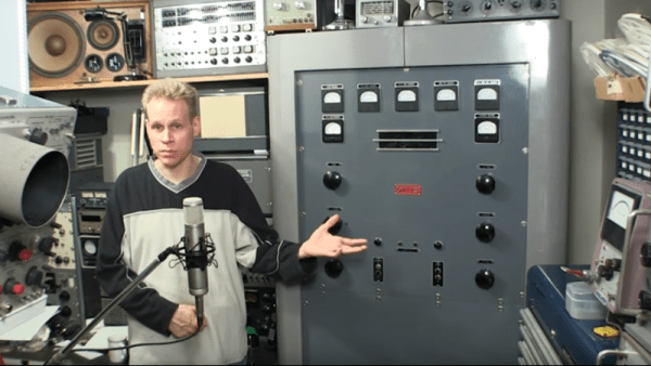
[Mr. Carlson] likes electronics gear. Mostly old gear. The grayer the case, the greener the phosphors, and the more hammertone, the better. That’s why we’re not surprised to see him with a mammoth AM radio station transmitter in his shop. That it’s a transmitter that you can walk into while it’s energized was a bit of a surprise, though.

As radio station transmitters go, [Mr. Carlson]’s Gates BC-250-GY broadcast transmitter is actually pretty small, especially for 1940s-vintage gear. It has a 250 watt output and was used as a nighttime transmitter; AM stations are typically required to operate at reduced power when the ionosphere is favorable for skip on the medium frequency bands. Stations often use separate day and night transmitters rather than just dialing back the daytime flamethrower; this allows plenty of time for maintenance with no interruptions to programming.

If you enjoy old broadcast gear, the tour of this transmitter, which has been rebuilt for use in the ham bands, will be a real treat. Feast your eyes on those lovely old bakelite knobs and the Simpson and Westinghouse meters, and picture a broadcast engineer in white short sleeves and skinny tie making notations on a clipboard. The transmitter is just as lovely on the inside — once the plate power supply is shut down, of course, lest [Mr. Carlson] quickly become [the former late Mr. Carlson] upon stepping inside. Honestly, there aren’t that many components inside, but what’s there is big – huge transformer, giant potato slicer variable caps, wirewound resistors the size of paper towel tubes, and five enormous, glowing vacuum tubes.

It’s a pretty neat bit of broadcasting history, and it’s a treat to see it so lovingly restored. [Mr. Carlson] teases us with other, yet larger daytime transmitters he has yet to restore, and we can’t wait for that tour. Until then, perhaps we can just review [Mr. Crosley]’s giant Cincinnati transmitter from the 1920s and wait patiently.

Continue reading “A Walk-In Broadcast Transmitter”

Turning Television Into A Simple Tapestry

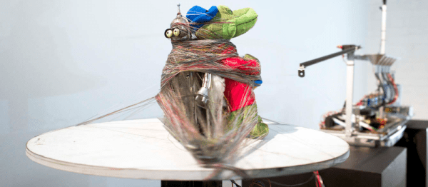
Teleknitting, the brainchild of Moscow artist [vtol], is an interesting project. On one hand, it doesn’t knit anything that is useful in a traditional sense, but on the other, it attempts the complex task of deconstructing broadcasted media into a simpler form of information transmission.

Teleknitting’s three main components are the processing and display block — made up of the antenna, Android tablet, and speaker — the dyeing machine with its ink, sponges, actuators, and Arduino Uno, and the rotating platform for the sacrificial object. A program running on the tablet analyzes the received signal and — as displayed on its screen — gradually halves the number of pixels in the image until there is only one left with a basic representation of the picture’s colour. From there, thread passes over five sponges which dye it the appropriate colour, with an armature that responds to the broadcast’s volume directing where the thread will bind the object.

Continue reading “Turning Television Into A Simple Tapestry”

Transmitting Analog TV, Digitally

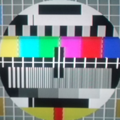
If you want to really understand a technology, and if you’re like us, you’ll need to re-build it yourself. It’s one thing to say that you understand (analog) broadcast TV by reading up on Wikipedia, or even by looking at scope traces. But when you’ve written a flow graph that successfully transmits a test image to a normal TV using just a software-defined radio, you can pretty easily say that you’ve mastered the topic.

9944491474271463115_thumbnail[Marble] wrote his flow for PAL, but it should be fairly easy to modify it to work with NTSC if you’re living in the US or Japan. Sending black and white is “easy” but to transmit a full color image, you’ll need to read up on color spaces. Check out [marble]’s project log.

Hackaday has another hacker who’s interested in broadcasting to dinosaur TVs: [CNLohr]. Check out his virtuoso builds for the ATtiny and for the ESP8266.

(Yes, the headline image is one of his earlier trials with black and white from Wikipedia — we just like the look.)

Retrotechtacular: Fog Over Portland

In the early days of broadcast television, national spectrum regulators struggled to reconcile the relatively huge bandwidth required by the new medium with the limited radio spectrum that could be allocated for it. In the USA during the years immediately following World War Two there was only a 12-channel VHF allocation, which due to the constraints of avoiding interference between adjacent stations led to an insufficient number of possible transmitter sites to cover the entire country. This led the FCC in 1949 to impose a freeze on issuing licences for new transmitters, and left a significant number of American cities unable to catch their I Love Lucy or The Roy Rogers Show episodes.

The solution sought by the FCC was found by releasing a large block of UHF frequencies between 470 and 890 MHz from their wartime military allocation, and thus creating the new channels 14 to 83. An experimental UHF pilot station was set up in Bridgeport, Connecticut in 1949, and by 1952 the FCC was ready to release the freeze on new licence applications. The first American UHF station to go on air was thus KPTV in Portland, Oregon, on September 18th of that year.

UHF TV was a very new technology in 1952, and was close to the edge of what could be achieved through early 1950s consumer electronics. Though the 525-line TV standard and thus the main part of the sets were the same as their VHF counterparts, the tuner designs of the time could not deliver the performance you might expect from more recent sets. Their noise levels, sensitivity, and image rejection characteristics meant that UHF TV reception  did not live up to some of its promise, and thus a fierce battle erupted between manufacturers all keen to demonstrate the inferiority of their competitors’ products over the new medium.

The video below the break delivers a fascinating insight into this world of claim and counter-claim in 1950s consumer electronics, as Zenith, one of the major players, fires salvos into the fray to demonstrate the superiority of their products over competing models or UHF converters for VHF sets. It’s very much from the view of one manufacturer and don’t blame us if it engenders in the viewer a curious desire to run out and buy a 1950s Zenith TV set, but it’s nonetheless worth watching.

A key plank of the Zenith argument concerns their turret tuner. The turret tuner was a channel selection device that switched the set’s RF front end between banks of coils and other components each preset to a particular TV channel. Zenith’s design had a unique selling point that it could be fitted with banks of components for UHF as well as VHF channels thus removing the need for a separate UHF tuner, and furthermore this system was compatible with older Zenith sets so existing owners had no need to upgrade. Particularly of its time in the video in light of today’s electronics is the section demonstrating the clear advantages of Zenith’s germanium mixer diode over its silicon equivalent. Undeniably true in that narrow application using the components of the day, but not something you hear often.

Continue reading “Retrotechtacular: Fog Over Portland”

Raspberry Pi Remote Audio Link

Hardware for remote audio link


In broadcast, lots of people are still using dedicated analog lines to connect remote sites. These operate like old telephone systems: you call up the operator and request to be patched through to a specific site. They’re also rather expensive.

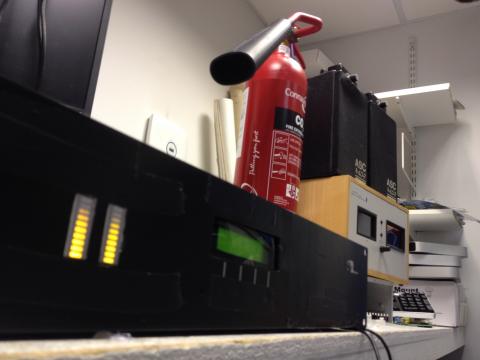
For a hospital radio station, [Marc] wanted to replace the old system with something less costly. The result is his Raspberry Pi STL in a Box. Inside the box is a Raspberry Pi, PiFace display, a pair of meters, and some analog hardware for the audio.

On the software side, the system uses LiquidSoap to manage the stream. LiquidSoap uses a language to configure streams, and [Marc] has a write-up on how to configure LiquidSoap for this application. On the hardware side, SSM2142 ICs convert the signal from single-ended to balanced. The meters use the LM3915 bar drivers to control the meters.

The Python script that controls the box is provided, and could be helpful for anyone needing to build their own low-cost audio link.


Stepper Directed HDTV Antenna

Credit: http://www.instructables.com/id/Computer-controlled-OTA-TV-antenna/

Broadcast TV has come a long way from adjusting the rabbit ears on top of the set just to get a fuzzy black and white picture. While nowadays there are often HD signals broadcast in most areas, it can often still be critical to redirect an antenna to get the best possible signal. By harvesting a stepper motor from an old 5 1/2″ floppy drive, and using a PC’s parallel port to control it, this adjustment can be handled automatically. Broadcast tower locations are easily found online, and once you have calibrated your stepper to face North, you are on your way to free HDTV reception.

What we would like to see is this antenna attached to a HTPC, and some kind of script to automatically direct the antenna for the best possible signal for the current channel. If anyone out there makes this happen, be sure to let us know.