Even from the very earliest days of the automobile age, cars and trucks have been hybrids of mechanical and electrical design. For every piston sliding up and down in a cylinder, there’s a spark plug that needs to be fired at just the right time to make the engine work, and stepping on the brake pedal had better cause the brake lights to come on at the same time hydraulic pressure pinches the wheel rotors between the brake pads.
Without electrical connections, a useful motor vehicle is a practical impossibility. Even long before electricity started becoming the fuel of choice for vehicles, the wires that connect the computers, sensors, actuators, and indicators needed to run a vehicle’s systems were getting more and more complicated by the year. After the engine and the frame, a car’s wiring and electronics are its third most expensive component, and it’s estimated that by 2030, fully half of the average vehicle’s cost will be locked in its electrical system, up from 30% in 2010.
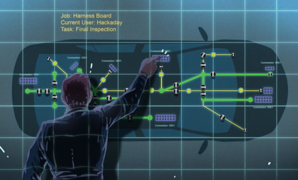
Making sure all those signals get where they’re going, and doing so in a safe and reliable way is the job of a vehicle’s wire harnesses, the bundles of wires that seemingly occupy every possible area of a modern car. The design and manufacturing of wire harnesses is a complex process that relies on specialized software, a degree of automation, and a surprising amount of people-power.
Continue reading “The Surprisingly Manual Process Of Building Automotive Wire Harnesses”