Update: Atari Pause Button

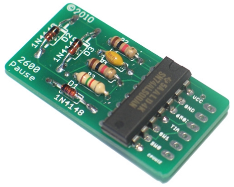
The Atari 2600 pause circuit is now available in a kit form. We saw this pause method back in February and the kit uses the same circuit. We don’t really need a kit for this, the board is very simple to throw together. But we do appreciate the detailed installation instructions (PDF) that accompany it. After all, you don’t want to kill you classic gaming rig with a botched install.

[Thanks CPUWIZ]

PCB Drill Press On A Budget

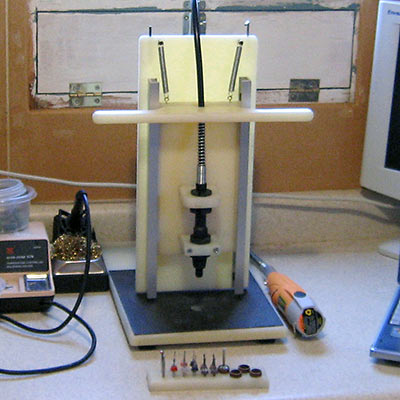
An accurate drill press is an essential tool for making your own through-hole printed circuit boards at home. Reader [Josh Ashby] offers up a solid design using scrap bin materials.

A major issue with PCB drilling is that even the slightest horizontal play will snap the delicate carbide drill bit. Hobbyist-grade tools such as Dremel’s drill press attachment are usually too sloppy for this task, while a more precise instrument might set you back a couple hundred bucks.

[Josh’s] design uses a nylon “sled” moving vertically in an aluminum u-channel track. Most of these materials were salvaged or were acquired inexpensively from a local hardware store, and assembled in less than a day. Surprisingly, this low-tech approach has proven sufficiently smooth that he’s yet to break a bit while drilling. And the entire setup, including the knockoff Harbor Freight rotary tool, cost less than the wobbly name-brand accessory alone.

Minimalistic Circuit Design

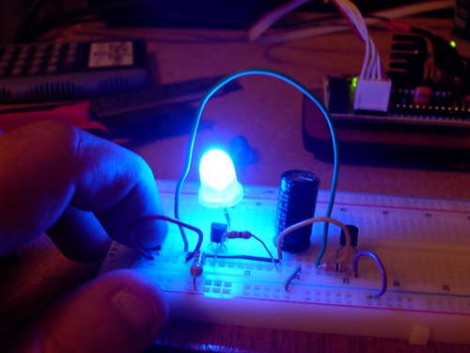
[David Terrill], whose exploits we have covered before, has shared with us his techniques for building circuits without a prototype or bread board. [David] managed to incorporate a Dual D flip-flop at the heart of the circuit, as well as an impressive number of transistors, diodes, and other passive components. Unfortunately, the circuit diagram is a little low resolution to really make out the real function, but based on the components, our best guess is a two-output blinking circuit. Maybe for an encore, someone out there will build a circuit built entirely around a battery so that it can be a self-contained system.

Let us know if you have a better copy of this schematic, or a guess at what the circuit does!

DIY Circuit Etching Video Tutorial

toner-paper

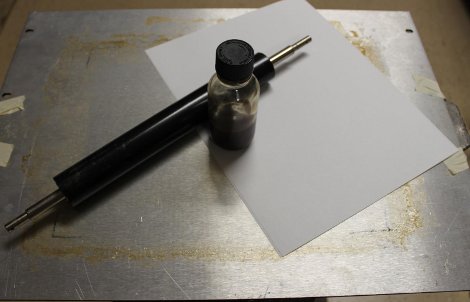
Circuit-bending blog GetLoFi has posted the best tutorial yet on home-made printed circuit boards using the toner transfer method.

We’ve covered homebrew PCB fabrication techniques about a billion times before. What sets this tutorial apart is that it collects many bits of knowledge otherwise scattered all about the web, and then depicts the entire process on video, from initial printing to cut PCB…because reading about it versus seeing it done are two different things entirely. They give a number of immensely useful tips throughout: choice of materials and where to get them, tools and techniques, and dispelling several myths about these methods (for example, they’re adamant about not using acetone to clean toner from the PCB). Well worth the 30 minutes to watch. If that’s too much and you’ve been stuck on just one part of the process, the tutorial is in three segments.

Trimming finished boards on a paper cutter? Who would’ve guessed?

[via Make]

PCB Toner Transfer With Dowel

Pulsar Professional FX has a neat tip on their site for getting a really even toner transfer when making your own PCBs. First, the PCB is cut to size, and the paper is tacked to the board. Then, the PCB is placed paper up onto a dowel and rolled back and forth with the iron. Since the board bends slightly over the dowel the toner sticks evenly to the copper. After that, just remove the paper as usual and etch with your preferred method.

Etch PCBs With Ferric Chloride And A Sponge

F7Z9JTTFX23V5VV

Etching a printed circuit board generally takes a bit of time and uses a lot of etchant. [TechShopJim] posted a method that uses a sponge to reduce the amount of etchant used while speeding up the entire process. First, a resist is applied using either a sharpie or the toner transfer method. Using gloves to handle everything, he soaked a sponge in ferric chloride and continually wiped a copper-clad board until all the exposed copper was removed. This technique moves the etchant around more, keeping “fresh” etchant closer to the copper. If you can’t procure ferric chloride, you can also use our method that uses 2 household chemicals: hydrogen peroxide and hydrochloric acid.

Printing Circuits On The RepRap

reprappcb

[Rhys Jones] has been working with the RepRap team to develop a way to print circuit boards. The machine first prints the plastic substrate with channels for the metal to be deposited into. They adapted their pinch wheel feeder to work with solid core solder (flux creates a mess). The extruded solder’s specific heat isn’t hot enough to melt the plastic. They made a video (embedded below) of their test piece: an optical endstop. The team has also been experimenting with decoupling the feed mechanism from the extruder.

Continue reading “Printing Circuits On The RepRap”