Colorizer For ZX81 Clone

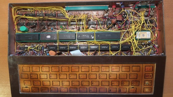
[danjovic] is a vintage computer enthusiast and has several old computers in his collection. Among them are a couple of TK-85 units – a ZX81 clone manufactured by Microdigital Eletronica in Brazil. The TK-85 outputs a monochrome video output. And when [danjovic] acquired a SyncMaster 510 computer monitor, he went about building a circuit to “colorise” the output from the ZX81 clone (Portuguese translation).

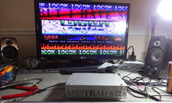
The SyncMaster 510 supports 15kHz RGB video refresh rate, so he thought it ought to be easy to hook it up to the TK-85, which internally has the video and composite sync signals available. So, if he could lower the amplitude of the video signal to 0.7Vpp, using resistors, and connect this signal to one of the primary colors on the monitor, for example green, then the screen should have black characters with a green background.

DSCN5584-thumb
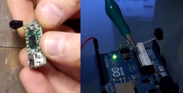
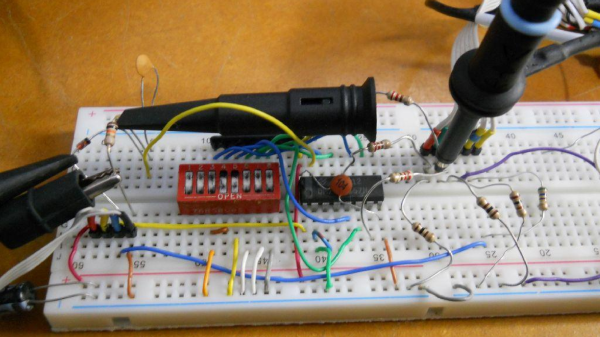
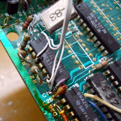
Before he could do any of this, he first had to debug and fix the TK-85 which seemed to be having several age related issues. After swapping out several deteriorating IC sockets, he was able to get it running. He soldered wires directly to one of the logic chips that had the video and sync signals present on them, along with the +5V and GND connections and hooked them up to a breadboard. He then tested his circuit consisting of the TTL multiplexer, DIP switches and resistors. This worked, but not as expected, and after some digging around, he deduced that it was due to the lack of the back porch in the video signal. From Wikipedia, “The back porch is the portion of each scan line between the end (rising edge) of the horizontal sync pulse and the start of active video. It is used to restore the black level (300 mV.) reference in analog video. In signal processing terms, it compensates for the fall time and settling time following the sync pulse.”

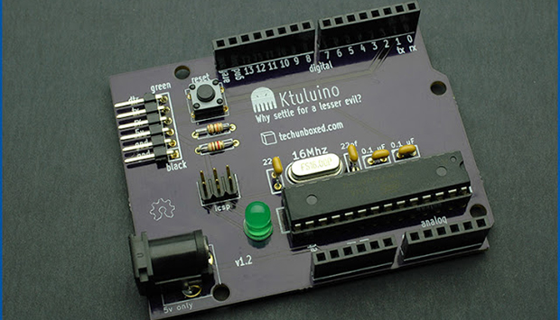
To implement the back porch, he referred to an older hack he had come across that involved solving a similar problem in the ZX81. Eventually, it was easily implemented by an RC filter and a diode. With this done, he was now able to select any RGB value for foreground and background colors. Finally, he built a little PCB to house the multiplexer, DIP switches and level shifting resistors. For those interested, he’s also documented his restoration of the TK-85 over a four-part blog post.

The RUM 80 – A Home Brew Z80 Computer Built From Scratch

[M] recently tipped us off about hacker [Lumir Vanek] from the Czech Republic. Between 1985 and 1989, [Lumir] built his own home brew, Z80 based computer. The list of home computers available in the 1980’s is extensive. Those living in western Europe and the Americas could choose offerings from Acorn, Apple, Commodore, Atari, Radio Shack, and Sinclair Research to name just a few. Even the erstwhile Czechoslovakia had home computers available from Didaktik and Tesla.

[Lumir]’s built was based around the Z80 processor and is built using regular, double-sided, prototyping board. It featured the 8-bit Z80 processor CPU, 8kB EPROM with monitor and BASIC, two Z80 CTC timers, an 8255 parallel interface for keyboard and external connector, 64kB DRAM, and Video output in black & white, 40×25 characters, connected to a TV. The enclosure is completely made from copper clad laminate. [Lumir] documented the schematics, but there is no board layout – since the whole thing was discrete wired. He even built the membrane keyboard – describing it as “layers of cuprextit, gum, paper with painted keys and transparent film”. When he ran out of space on the main board, he built an expansion board. This had an 8251 serial interface for cassette deck, one 8-bit D/A converter, and an 8255 parallel port connected to the “one pin” BT100 printer.

On the software side, he wrote his own monitor program, which allowed simple interactions, such as displaying and modifying registers, memory, I/O ports and to run programs. He wrote this from scratch referring to the Z80 instruction set for help. Later he added a CP/M emulator. Since the Z80 had dual registers, one was used for user interaction, while the other was reserved to allow background printing. Eventually, he even managed to port BASIC to his system.

Check out [Martin Malý]’s awesome article Home Computers behind the Iron Curtain and the follow up article on Peripherals behind the  Iron Curtain, where you can read more about the “one pin” BT100 printer.

Continue reading “The RUM 80 – A Home Brew Z80 Computer Built From Scratch”

A Smaller, Homebrew Amstrad

Although they weren’t very popular in America, the Amstrad CPC 464 and CPC 6128 were extremely well-received in Europe. [Zaxon] loved his ‘464, and for a bit of a learning experience – and the fact that an Amstrad takes up an exceptional amount of desk space – decided to make a clone of his favorite computer (.pl, Google translatrix).

The clone began as a simple schematic of the original Amstrad CPC 464, but the parts used in the original required some modern equivalents. Still, most of the old chips remained in the clone; the original Hitachi HD46505 CRT controller remains, as do the original DRAM chips and the vintage Z80 CPU.

A few modern amenities were added, including an interface for a PS/2 keyboard and a disk that’s much improved over the original cassette drive or weird 3.5″ disks: a Disk On Module, or basically a CompactFlash card in a strange form factor that plugs straight into a motherboard’s IDE socket. They’re mostly seen when tearing apart old thin clients, but using them in retrocomputing project is a great idea.

Thanks [rasz_pl] for the tip. Video below.

Continue reading “A Smaller, Homebrew Amstrad”

A Real Raspberry Pi Clone (Not ‘Inspired By’)

odroid 
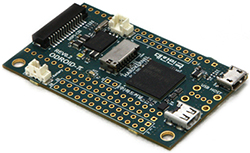
A few years ago, Broadcom had a pretty nice chip – the BCM2835 – that could do 1080 video, had fairly powerful graphics performance, run a *nix at a good click, and was fairly cheap. A Broadcom employee thought, “why don’t we build an educational computer with this” and the Raspberry Pi was born. Since then, Broadcom has kept that chip to themselves, funneling all of them into what has become a very vibrant platform for education, tinkering, and any other project that could use a small Linux board. Recently, Broadcom has started to sell the BCM2835 to anyone who has the cash and from the looks of it, real Raspberry Pi clones are starting to make their way into the marketplace.

Other Raspberry Pi clone boards out there like the Banana Pi and the HummingBoard don’t use the same BCM2835 found in the Raspi and the new Odroid. The new board also has the same 26 pin GPIO expansion socket, and runs the same binaries as the Raspberry P;. It is a clone in every sense, with a slightly different form factor geared towards very tiny, portable, and battery-powered use cases.

Unlike the official Raspberry Pi Compute Module, the Odroid isn’t meant to be used as a system on module, shoved into any product that needs a fast-ish ARM core without needing engineers to actually design a circuit with an ARM. The Odroid is a cut-down, extremely minimalist version of the Raspi, perfect for any project where space is at a premium.

There are a few interesting features included on the Odroid: there’s an on-board battery connector, a real-time clock on the board, and more of the BCM2835 GPIOs are exposed (although not the same ones as the upgraded RPi Model B+). There’s no Ethernet, but odds are if you’re building something that’s battery-powered, you won’t need that anyway.

As far as price goes, you can pick one of these Odroids up for $30 USD, with $9 shipping from South Korea. That’s pretty comparable to the price of a real Raspberry Pi, but if the features in the Odroid are worth it to you, it might be a worthwhile clone.

Primer Tutorials For Arduino IR Remote Cloning And Keyboard Simulation

We’ve featured loads of IR Arduino projects and they are all exciting and unique. The projects spring from a specific need or problem where a custom infrared remote control is the solution. [Rick’s] double feature we’re sharing in this article is no exception, but what is interesting and different about [Rick’s] projects is his careful and deliberate tutorial delivery on how to copy infrared remote codes, store the codes with a flavor of Arduino and then either transmit or receive the codes to control devices.

In the case of his space heater an Arduino was used to record and later retransmit the “power on” IR code to the heater before he awakes on a cold morning. This way his room is toasty warm before he has to climb out from under the covers, which has the added benefit of saving the cost of running the heater all night. Brilliant idea if you don’t have a programmable heating system. Maybe he will add a temperature sensor someday so it doesn’t have to run on strictly time.

A more complicated problem was controlling DVD playback software on his computer remotely. [Rick] says he sits at a distance when watching DVDs on his computer but his computer doesn’t have a remote control like a normal TV. Arduino to the rescue again! But this time he pulls out a Teensyduino because of its added feature of being able to emulate a keyboard and of course the computer DVD playback software accepts keyboard commands. Once again he used the “IRremote.h” library to record certain button codes from an old remote control before adding the retrieved codes to a Teensyduino setup and programmed to receive and decode the remote’s IR signals. The Teensyduino then maps the IR codes to known keyboard shortcuts and transmits the simulated keyboard shortcut commands to the computer via its USB cable where the DVD playback software recognizes the key commands.

As always [Rick] shares all his libraries and sketches on his blog so follow the above links to download the files. You will not miss a single step if you follow his excellent videos below. Plus, here are some other ways and other tools for using an IR remote with your Arduino and cloning an infrared remote.

Continue reading “Primer Tutorials For Arduino IR Remote Cloning And Keyboard Simulation”

Another Arduino Clone Is The Last Thing The World Needs

duino

One might think the last thing the world needs is for The Great Old Ones to rise from their near-death sleep deep in the Pacific ocean, and begin again their reign over Earth.  Actually, the last thing the world needs is another Arduino clone. Here’s this one. Fittingly, it’s called the Ktuluino.

Actually, this isn’t yet another attempt to build an Arduino clone that adds nothing to existing designs; it’s just [Jeff]’s attempt at PCB design. He needed something to practice on, so why not something that ends in -uino?

The board is just about as simple as Arduinos come – an ATMega328P is the brains of the outfit and also the most expensive component, closely followed by either the power jack or the header pins. As an exercise in PCB design, we’ll give this a thumbs up, but this could also be used for an ‘introduction to soldering’ workshop at a hackerspace, or alternatively a coaster.

Saleae Logic Analyzer Knockoff Hacking

Despite what this module says on the case, it’s certainly not official Saleae Logic Analyzer hardware. [Jack Andrews] picked up this Chinese knockoff on eBay for about $18. When plugged into the computer the Saleae software picks it up as the official hardware. But [Jack] has seen other knockoffs which have a jumper to select between Saleae cloning and USBee cloning so he found a way to switch software with this dongle.

He pulled the board out of the case and discovered a Cypress CY7C68013A microcontroller on a poorly-soldered board (imagine that). This is an 8051-compatible processor that includes USB functionality. There’s also an EEPROM on the bottom of the board which stores the VID/PID pair identifying it as Saleae Logic hardware. The trick to getting this working with the USBee software is to change that pair. [Jack] managed to do this without an external programmer. He uninstalled the Saleae driver and installed a Cypress driver. Then he wrote a bit of code for the CY7C68013A to rewrite the EEPROM and flashed it via the USB connection. Now the dongle enumerates as USBee Logic Analyzer hardware.