Ideal Diodes And How To Build Them

[Julian] knows that real diodes you can buy don’t work exactly like we say they do. That’s actually pretty common. We routinely ignore things like wire resistance and source resistance in batteries. Diodes have problems that are harder to ignore, such as the forward voltage drop. So, while a real diode will only pass current in one direction, it will also drop some of the voltage. [Julian] shows you how you can get simulated ideal diodes and why you might want them in a recent video you can see below.

The video starts with a simple demonstration and enumerates some of the practical limitations. Then, he pulls out some ideal diode modules. These typically don’t solve every problem, so they aren’t really ideal in the theoretical sense. But they typically appear to have no forward voltage drop.

Continue reading “Ideal Diodes And How To Build Them”

How Do You Fill The 1N34 Void?

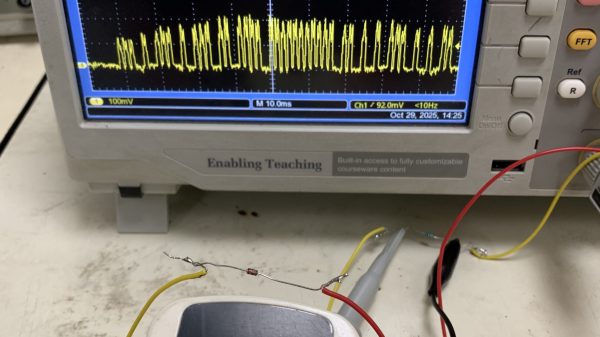
The germanium point contact diode, and almost every semiconductor device using germanium, is now obsolete. There was a time when almost every television or radio would have contained one or two of them, but the world has moved on from both analogue broadcasting and discrete analogue electronics in its lower-frequency RF circuitry. [TSBrownie] is taking a look at alternatives to the venerable 1N34A point-contact diode in one of the few places a point-contact diode makes sense, the crystal radio.

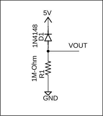
In the video below the break, he settles on a slightly more plentiful Eastern European D9K as a substitute after trying a silicon rectifier (awful) and a Schottky diode (great in theory, not so good in practice). We’ve trodden this path in the past and settled on a DC bias to reduce the extra forward voltage needed for a 1N4148 silicon diode to conduct because, like him, we found a Schottky disappointing.

The 1N34 is an interesting component, and we profiled its inventor a few years ago. Meanwhile, it’s worth remembering that sometimes, we just have to let old parts go.

Continue reading “How Do You Fill The 1N34 Void?”

MOSFET Heater Is Its Own Thermostat

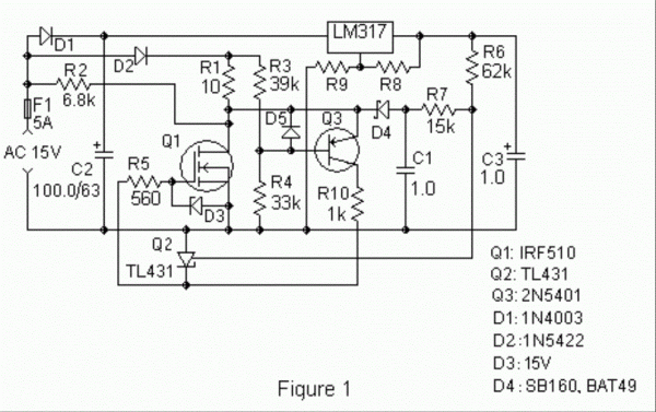
While we might all be quick to grab a microcontroller and an appropriate sensor to solve some problem, gather data about a system, or control another piece of technology, there are some downsides with this method. Software has a lot of failure modes, and relying on it without any backups or redundancy can lead to problems. Often, a much more reliable way to solve a simple problem is with hardware. This heating circuit, for example, uses a MOSFET as a heating element and as its own temperature control.

The function of the circuit relies on a parasitic diode formed within the transistor itself, inherent in its construction. This diode is found in most power MOSFETs and conducts from the source to the drain. The key is that it conducts at a rate proportional to its temperature, so if the circuit is fed with AC, during the negative half of the voltage cycle this diode can be probed and used as a thermostat. In this build, it is controlled by a set of resistors attached to a voltage regulator, which turn the heater on if it hasn’t reached its threshold temperature yet.

In theory, these resistors could be replaced with potentiometers to allow for adjustable heat for certain applications, with plastic cutting and welding, temperature control for small biological systems, or heating other circuits as target applications for this type of analog circuitry. For more analog circuit design inspiration, though, you’ll want to take a look at some classic pieces of electronics literature.

Copper: Rectifying AC A Century Ago

[Robert Murray-Smith] presents for us an interesting electronic device from years gone by, before the advent of Silicon semiconductors, the humble metal oxide rectifier. After the electronic dust had settled following the brutal AC/DC current wars of the late 19th century — involving Edison, Tesla and Westinghouse to name a few of the ringleaders — AC was the eventual winner. But there was a problem. It’s straightforward to step down the high voltage AC from the distribution network to a more manageable level with a transformer, and feed that straight into devices which can consume alternating current such as light bulbs and electrical heaters. But other devices really want DC, and to get that, you need a rectifier.

It turns out, that even in those early days, we had semiconductor devices which could perform this operation, based not upon silicon or germanium, but copper. Copper (I) Oxide is a naturally occurring P-type semiconductor, which can be easily constructed by heating a copper sheet in a flame, and scraping off the outer layer of Copper (II) Oxide leaving the active layer below. Simply making contact to a piece of steel is sufficient to complete the device.

Obviously a practical rectifier is a bit harder to make, with a degree of control required, but you get the idea. A CuO metal rectifier can rectify as well as operate as a thermopile, and even as a solar cell, it’s just been forgotten about once we got all excited about silicon.

Other similar metallic rectifiers also saw some action, such as the Selenium rectifier, based on the properties of a Cadmium Selenide – Selenium interface, which forms an NP junction, albeit one that can’t handle as much power as good old copper. One final device, which was a bit of an improvement upon the original CuO rectifiers, was based upon a stack of Copper Sulphide/Magnesium metal plates, but they came along too late. Once we discovered the wonders of germanium and silicon, it was consigned to the history books before it really saw wide adoption.

We’ve covered CuO rectifiers before, but the Copper Sulphide/Magnesium rectifier is new to us. And if you’re interested in yet more ways to steer electrons in one direction, checkout our coverage of the history of the diode.

Continue reading “Copper: Rectifying AC A Century Ago”

A 7805 Regulator puts out 6.3 Volts

Simple Electronic Hacks Inspire Doing More With Less

It’s late at night. The solder smoke keeps getting in your tired eyes, but your project is nearly done. The main circuit is powered by your 13.8 V bench supply, but part of the circuit needs 9 V. You dig into your stash to find your last LM7809 voltage regulator, but all you have is a bunch of LM7805’s. Are you done for the night? Not if you’ve watched [0033mer]’s Simple Electronic Circuit Hacks video! You know just what to do. The ground pin of a LM7805 connects to the cathode of a TL431 programmable Zener diode pulled from an old scrapped TV. The diode is referenced to a voltage divider, and voila! Your LM7805 is now putting out a steady 9 V.

How did [0033mer] become adept at doing more with less? As he explains in the video below, his primary source of parts in The Time Before The Internet was old TV’s that were beyond repair. Using N-Channel MOSFETs to switch AC, sensing temperature changes with signal diodes, and even replacing a 555 with a blinking LED are just a few of the hacks covered in the video below the break.

We especially appreciated the simple, to-the-point presentation that inspires us to keep on hacking in the truest sense: Doing more with less! If you enjoy a good diode hack like we do, you will likely appreciate learning Diode Basics by W2AEW, or a Diode Based Radiation Detector.

Thank you [DSM] for the tip! Be sure to submit your the cool things you come across to our Tips Line!

Continue reading “Simple Electronic Hacks Inspire Doing More With Less”

What Goes Into A High Voltage Diode?

When we use an electronic component, we have some idea of what goes on inside it. We know that inside a transistor there’s a little piece of semiconductor with a junction made from differently doped regions etched into it, and in a capacitor, there will be metalized plates on the surface of some kind of dielectric. Reverse engineering has given us extensive die photography of integrated circuits, but there remain a few component mysteries to be uncovered. One is laid bare by [WizardTim], as he cross-sections a 20KV high-voltage diode.

A conventional low-voltage silicon diode has a forward voltage drop of about 0.7V and a relatively low maximum reverse voltage, for example with the 1N4001 rectifier it’s 50V.  For the higher-spec 1N4007, the reverse voltage rating is 700V. This diode has a 25KV reverse voltage, and a clue to its construction comes in its quoted 45V forward voltage. Sure enough, when mounted in resin and carefully sanded and polished flat it reveals its interior as a stack of diodes in series to increase the reverse voltage at the expense of forward voltage.

Revealing the inner workings of an unusual component is fascinating, and the lapping technique used is definitely worth a look. It’s something we’ve seen before, for example in reducing CPU thickness for increased performance.

Continue reading “What Goes Into A High Voltage Diode?”

Reverse Engineering A Module From A Vacuum Tube Computer

It’s best to admit upfront that vacuum tubes can be baffling to some of the younger generation of engineers. Yes, we get how electron flow from cathode to anode can be controlled with a grid, and how that can be used to amplify and control current. But there are still some things that just don’t always to click when looking at a schematic for a tube circuit. Maybe we just grew up at the wrong time.

Someone who’s clearly not old enough to have ridden the first wave of electronics but still seems to have mastered the concepts of thermionic emission is [Usagi Electric], who has been doing some great work on reverse engineering modules from old vacuum tube computers. The video below focuses on a two-tube pluggable module from an IBM 650, a machine that dates clear back to 1954. The eBay find was nothing more than two tube sockets and a pair of resistors joined to a plug by a hoop of metal. With almost nothing to go on, [Usagi] was still able to figure out what tubes would have gone in the sockets — the nine-pin socket was a big clue — and determine that the module was likely a dual NAND gate. To test his theory, [Usagi] took some liberties with the original voltages used by IBM and built a breakout PCB. It’s an interesting mix of technologies, but he was able to walk through the truth table and confirm that his module is a dual NAND gate.

The video is a bit long but it’s chock full of tidbits that really help clear up how tubes work. Along with some help from this article about how triodes work, this will put you on the path to thermionic enlightenment.

Continue reading “Reverse Engineering A Module From A Vacuum Tube Computer”