A mechanism made of brass and steel is attached to a milling machine. It has a long lever extending from the right side, a counterweight attached to the left side, and an indicator gauge in the middle.

A Precision Drill Press For Tiny Bits

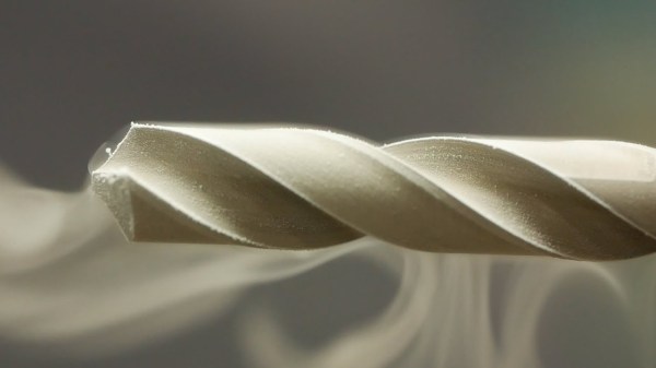
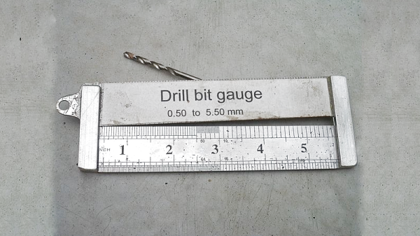
Anyone who’s worked with even a 1 mm bit knows that while a drill press is all but essential, it isn’t proof against broken bits. Working with a 0.1 mm drill bit seems, therefore, all but impossible, which is why [Mike] of Chronova Engineering built this mechanism to simplify such drilling.

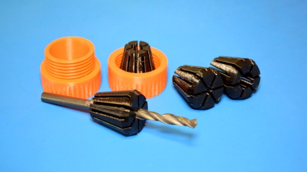
The mechanism is an attachment for a milling machine, and in principle it just needs to move the rotating drill bit up and down. It needs to be extremely precise, though. For context, a good-quality chuck normally has a runout of 30 to 50 microns, which is approaching half the diameter of the drill bit. The mechanism has a collet mounted in the milling machine’s spindle, which transfers rotation to a second spindle. The second spindle is mounted to a runout-compensating drill chuck, and is connected to a lever and counterweight which allow the user to make small, low-force movements. A dial indicator lets the user see how far the bit’s descended.

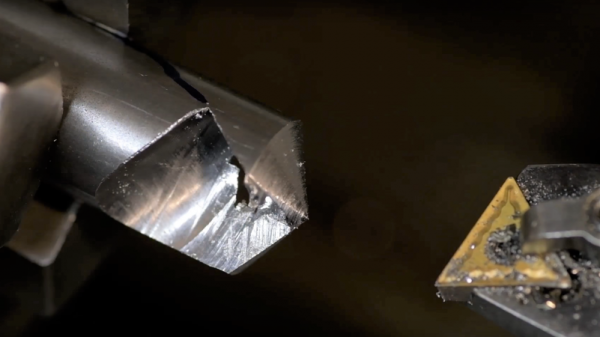
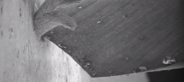
Most of the parts were machined out of steel or brass, with the handle being made of titanium for lower weight. When the finished device was mounted to the milling machine, the measured runout was severe. After much investigation and reworking, however, the problem turned out to be a damaged collet locating pin, not an issue with the drilling mechanism. As a first test, [Mike] drilled a 0.1 mm hole 1.8 mm deep, then as a challenge drilled six 0.1 mm holes in the end of a thin steel wire. The results weren’t quite as uniform as he wanted, but it took a scanning electron microscope to even see the imperfection.

It won’t help much with very fine drill bits, but if you need a very precisely-placed hole, check out this periscopic drilling camera. If you do break a drill bit in the workpiece, you might be able to dissolve it with alum.

Continue reading “A Precision Drill Press For Tiny Bits”

Printed It: Collet Drill Stop

You’d think that being quarantined in your home would be perfect for hackers and makers like us, as we all have a project or two that’s been sitting on the back burner because we didn’t have the time to tackle it. Unfortunately, some are finding that the problem now is actually getting the parts and tools needed to do the job. When there’s a bouncer and a line outside the Home Depot like it’s a nightclub on Saturday night, even the simplest of things can be difficult to source when making in the time of COVID.

Which is exactly the situation I found myself in recently when I needed to drill a bunch of holes to the same depth. The piece was too big to put in the drill press, and while I contemplated just wrapping the bit in some tape to serve as a makeshift stop, I wasn’t convinced it would be accurate or repeatable enough. It occurred to me that a set of drill stop collars would be easy enough to design and 3D print, but before I fired up OpenSCAD, I decided to see what was already available online.

Which is how I found the “Collet Drill Stop” from Adam Harrison. Rather than the traditional ring and setscrew arrangement, his design uses a printable collet that will clamp down on the bit at an arbitrary position without tools. So not only could I avoid a trip to the store by printing this design out, it looked like it would potentially be an upgrade over what I would have bought.

Of course, it’s wise not to take anything for granted when dealing with 3D printing. The only way I could be sure that Adam’s design would work for me was to commit it to plastic and try it out.

Continue reading “Printed It: Collet Drill Stop”

Reducing Drill Bit Wear The Cryogenic Way

There are a lot of ways that metals can be formed into various shapes. Forging, casting, and cutting are some methods of getting the metal in the correct shape. An oft-overlooked aspect of smithing (at least by non-smiths) is the effect of temperature on the final characteristics of the metal, such as strength, brittleness, and even color. A smith may dunk a freshly forged sword into a bucket of oil or water to make the metal harder, or a craftsman with a drill bit might treat it with an extremely cold temperature to keep it from wearing out as quickly.

Welcome to the world of cryogenic treatment. Unlike quenching, where a hot metal is quickly cooled to create a hard crystal structure in the metal, cryogenic treatment is done by cooling the metal off slowly, and then raising it back up to room temperature slowly as well. The two processes are related in that they both achieve a certain amount of crystal structure formation, but the extreme cold helps create even more of the structure than simply tempering and quenching it does. The crystal structure wears out much less quickly than untreated steel, therefore the bits last much longer.

[Applied Science] goes deep into the theory behind these temperature treatments on the steel, and the results speak for themselves. With the liquid nitrogen treatments the bits were easily able to drill double the number of holes on average. The experiment was single-blind too, so the subjectivity of the experimenter was limited. There’s plenty to learn about heat-treated metals as well, even if you don’t have a liquid nitrogen generator at home.

Thanks to [baldpower] for the tip!

Continue reading “Reducing Drill Bit Wear The Cryogenic Way”

Drill Bit Gauge Is Interdenominational Black Magic

Oh, sure – when you buy a new set of drill bits from the store, they come in a handy holder that demarcates all the different sizes neatly. But after a few years when they’ve ended up scattered in the bottom of your toolbox for a while, it becomes useful to have some sort of gauge to measure them. [Caspar] has the solution, and all you need is an old steel rule.

The trick is to get a ruler with gradations for inches and tenths of inches. After cutting the ruler off just after the 6″ point, the two halves are glued together with some steel offcuts and epoxy. By assembling the two halves in a V shape with a 1 mm drill bit at the 1″ position, and a 5 mm drill bit at the 5″ marker, a linear slope is created that can be used to measure any drill bits and rod of the appropriate size inserted between the two.

It’s a handy tool to have around the shop when you’ve amassed a collection of bits over the years, and need to drill your holes accurately. Additionally, it’s more versatile than the usual method of inserting bits in appropriately sized holes, and can be more accurate.

Now that you’ve organised your drill bits, perhaps you’d like to sharpen them?

Sharpening Drills Bits The Hard Way

Drill bits are so cheap that when one is too chowdered up to keep working, we generally just toss it out. So you might expect a video on sharpening drill bits to be somewhat irrelevant, but [This Old Tony] makes it work.

The reason this video is worth watching is not just that you get to learn how to sharpen your bits, although that’s an essential metalworker’s skill. Where [This Old Tony]’s video shines is by explaining why a drill bit is shaped the way it is, which he does by fabricating a rudimentary twist drill bit from scratch. Seeing how the flutes and the web are formed and how all the different angles interact to cut material and transport the swarf away is fascinating. And as a bonus, knowing what the angles do allows you to customize a grind for a special job.

[This Old Tony] may be just a guy messing around in his shop, but he’s got a wealth of machine shop knowledge and we always look forward to seeing what he’s working on, whether it’s a homemade fly cutter or a full-blown CNC machine.

Continue reading “Sharpening Drills Bits The Hard Way”

Scanning Electron Microscope Images And Animations Pulled By Impressive Teensy LC Setup

When you’ve got a scanning electron microscope sitting around, you’re going to find ways to push the awesome envelope. [Ben Krasnow] is upping his SEM game with a new rig to improve image capture (video link) and more easily create animated GIFs and videos.

The color scheme of the SEM housing gives away its 80s vintage, and the height of image capture technology back then was a Polaroid camera mounted over the instrument’s CRT. No other video output was provided, so [Ben] dug into the blueprints and probed around till he found the high-resolution slow scan signal.

To make his Teensy-LC happy, he used a few op-amps to condition the analog signal for the greatest resolution and split out the digital sync signals, which he fed into the analog and digital ports respectively. [Ben] then goes into a great deal of useful detail on how he got the video data encoded and sent over USB for frame capture and GIF generation. Reading the ADC quickly without jitter and balancing data collection with transmission were tricky, but he has established a rock-solid system for it.

Continue reading “Scanning Electron Microscope Images And Animations Pulled By Impressive Teensy LC Setup”