Reproducing A DSKY

This is a project that is about a year and a half in the making, but [Fran] is finally digging into the most iconic part of the Apollo Guidance Computer and building the most accurate reproduction DSKY ever.

The Apollo Guidance Computer was a masterpiece of engineering and is frequently cited as the beginning of the computer revolution, but it didn’t really look that interesting – it looks like a vastly overbuilt server blade, really. When everyone thinks about the Apollo Guidance Computer, they think about the DSKY, the glowey keypad interface seen in the blockbuster hit Apollo 13 and the oddly accurate disappointment of Apollo 18. It’s the part of the Apollo Guidance Computer the Apollo astronauts actually interacted with, and has become the icon of the strange, early digital computers developed for NASA in the 60s.

There are a few modern DSKY replicas, but all of them are exceedingly anachronistic; all of these reproductions use seven-segment LEDs, something that didn’t exist in the 1960s. A true reproduction DSKY would use custom electroluminescent displays. These EL segments are powered by AC, and transistors back then were terrible, leading to another design choice – those EL segments were turned on and off by relays. It’s all completely crazy, and aerospace equipment to boot.

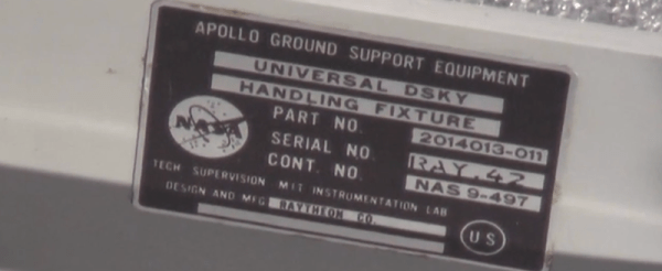
Because of the custom design and engineering choices that seem insane to the modern eye, there isn’t much in the way of documentation when it comes to making a reproduction DSKY. This is where [Fran] tapped a few of the contacts her historical deconstruction cred earned when she reverse engineered a Saturn V Launch Vehicle Digital Computer to call upon anyone who would have access to a real Apollo-era DSKY.

The first contact was the Kansas Cosmosphere who was kind enough to send extremely detailed photographs of the DSKYs in their archives. It would have been extremely nice to have old documentation made when the DSKYs were rolling off the assembly line, but that information is locked away in a file cabinet owned by Raytheon.

[Fran] got a break when she was contacted by curators at the National Air and Space Museum’s Garber facility who invited her down to DC. She was given the grand tour, including the most elusive aircraft in the museum’s collection, the Ho 229, the dual-turbojet Nazi flying wing. At the Garber facility, [Fran] received permission to take apart two DSKYs.

The main focus of [Fran]’s expedition to the Air and Space Museum was to figure out how the EL displays were constructed. The EL displays that exist today are completely transparent when turned off because of the development of transparent conductors.

The EL displays in the DSKY were based on earlier night lights manufactured by Sylvania. After looking at a few interesting items that included Gemini hardware and early DSKYs, this sort of construction was confirmed.

With a lot of pictures, a lot of measurements, a lot of CAD work, and some extremely tedious work, [Fran] was able to create the definitive reference for DSKY display elements. There are 154 separate switchable element in the display, all controlled by relays. These elements are not multiplexed; every element can be turned on and off individually.

Figuring out how the elements were put together was only one part of [Fran]’s research. Another goal was to figure out the electrical connections between the display and the rest of the DSKY. There, [Fran] found 160 gold pins in a custom socket. It’s bizarre, and more like a PGA socket than like the backplane connector [Fran] found in the Saturn V computer.

Even though [Fran]’s research was mostly on the EL panel inside the display, she did get a few more insights with her time with the DSKYs. The buttons are fantastic, and the best keys she’d ever used. This is just part one of what will be an incredibly involved project, and we’re looking forward to what [Fran] looks into next.

Building EL Displays On A PCB

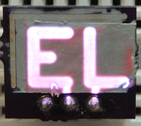
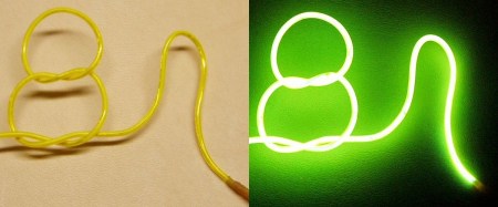
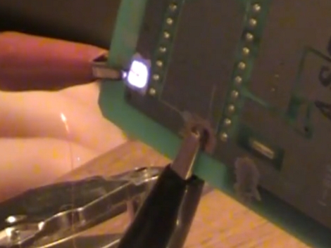
ELElecrolumiscent displays have seen a huge swing in popularity recently, but only in limited forms like EL wire or flat EL panels. You can, of course, cut and bend these wires and panels to suit any purpose, but custom shaped EL displays are just the bee’s knees. They’re not hard to fabricate, either: with cheap custom PCBs, all it takes to make custom EL panels is just a few chemicals.

[Nick]’s method of fabricating custom EL displays uses an exposed copper layer on a PCB you’d pick up from OSHpark or any of the random board houses in China. The process consists of designing a display – be it a few letters, pixels, or a seven-segment arrangement. The display ‘stack’ is a layer of painted-on dialectric, a phospor, and finally a translucent conductive ink that connects the display segments to ground. It looks like an extremely easy process, and from the pictures it looks like [Nick] is making some EL displays of reasonable quality.

[Nick]’s work was inspired by the grand poobah of homebrew electrolumiscent displays, [Jeri Ellsworth], who managed to make a similar EL pixel on a PCB. [Nick]’s display looks great, though, and with a little work some custom segment displays should be very possible.

High Voltage Hacks: All About Electroluminescence

Although many might not know it, electroluminescent materials use high voltage, and thus qualify for our featured topic. Many may assume that these sheets work in the same way as LED lights, using low-voltage DC power.  This, however, is not the case, as they need around 100 volts of AC current to allow them to light up.

For a battery-powered solution, this means converting the battery’s DC power to AC. Adafruit has a good tutorial about working with EL wire and powering it up using a portable inverter. One should obviously be careful to properly insulate any clothing using this material as being shocked is generally not fun.

The video after the break is pretty long, but is well produced and will give you a good background of EL use. If you don’t have 30 minutes to dedicate to this, be sure to at least skip to 2:43 to see one of the coolest EL shirts we’ve seen. Continue reading “High Voltage Hacks: All About Electroluminescence”

Jeri Makes Flexible EL Displays

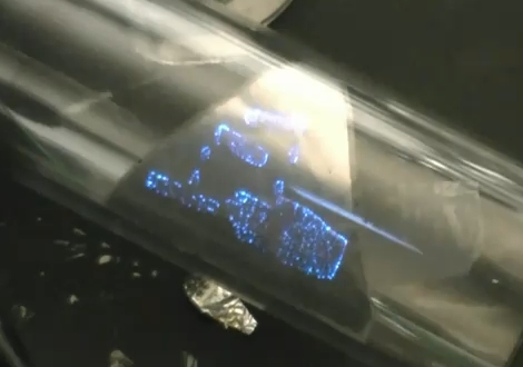
A failed chemistry experiment led [Jeri Ellsworth] to discover a flexible substrate for electroluminescent displays. We’re familiar with EL displays on the back of a glass panel like you would find in an audio receiver, but after making a mesh from aluminum foil [Jeri] looked at using the porous metal to host phosphors. She starts by cleaning foil and using a vinyl sticker to resist etching portions of the aluminum. It then goes into a bath of boric acid, electrified with the foil as the anode. As the foil etches she tests the progress by shining a laser through the foil. After this the phosphors are applied to the back surface of the foil, covered in a dielectric, and topped off with a conductive ink that will carry the AC necessary to excite the phosphors. This is layering materials in reverse compared to her EL PCB experiments. See [Jeri] explain this herself in the clip after the break.

You can see above that this produces a pretty well-defined display area. It reminds us of that color changing paint display. We think it would be worth a try to build a few 7-segment displays using this method.

Continue reading “Jeri Makes Flexible EL Displays”

More EL Chemistry: Luminescent Ink

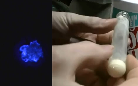
[Jeri Ellsworth] continues her experiments with electroluminescence, this time she’s making EL ink. The ink she’s looking for is Zinc Sulfate in a solution. The process she chose is to re-dope some glow powder so that it can be excited by the field around an AC current. In her video (embedded after the break) she talks about the chemical properties she’s after by detailing a cubic lattice of zinc and sulfur atoms with an added copper atom (adding that atom is a process called doping).

The quick and dirty synopsis of the experiment starts by washing the glow powder with dish soap to acquire zinc sulfide crystals. Then she combined copper sulfate and zinc shavings from the inside of a modern penny to yield copper metal and zinc sulfate suspended in solution. That was mixed with the zinc sulfide from the glow powder washing and doped with a little more copper sulfate. The excess liquid is poured off, the test tube is capped with glass frit, and the whole thing hits the kiln to start the reaction. The result glows when excited by alternating current, but could have been improved by adding chlorine atoms into the mix.

We’re excited every time we see one of [Jeri’s] new chemistry hacks. We’d love to see more so if you’ve come across interesting chemistry experiments during your Internet travels, please let us know about them. Just make sure you have some idea of what you’re doing when working with chemicals… safety first.

Continue reading “More EL Chemistry: Luminescent Ink”

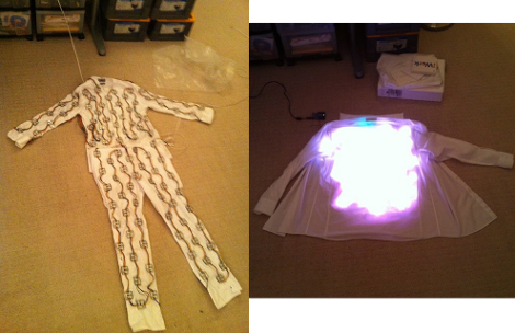
LED Suit Lights Up The Night

When the tipline popped up with this LED suit, part two, by [Marc DeVidts] we were expecing a simple led version of the previously known EL coat.

Well we were right and wrong in the same instance. Correct in that like predictions, the outcome is stonking great. Wrong in that this suit far outpaces EL in abilities we weren’t expecting. Namely to start off, an iPhone app over WiFi dictates to some 200 Arduino multiplexed RGB LED modules to dance randomly or follow patterns; an accelerometer and microphone are also implanted to further some effects. And finally if the suit isn’t enough to make you giddy, his PCB and enclosure milling surely will. Catch a video of the entire setup after the break.

Continue reading “LED Suit Lights Up The Night”

EL Wire: Make It, Connect It, Power It

[Jeri’s] back with a series of videos that outlines the step-by-step electroluminescent wire manufacturing, making EL panels from PCBs, and assembling power supplies for EL hardware. These concepts are actually quite approachable, something we don’t expect from someone who makes their own integrated circuits at home.

The concept here is that an alternating current traveling through phosphors will excite them and produce light. You need two conductors separated by a dielectric to get the job done. For wire, [Jeri] uses one strand of enameled magnet wire and one strand of bare wire. The enamel insulates them, protecting against a short circuit.

But that’s not all, she also tests using a circuit board as an EL panel. By repurposing the ground plane as one of the conductors, and using the solder mask as the dielectric she is able to paint on a phosphor product resulting in the glowing panel.

Finally, you’ve got to get juice to the circuit and that’s where her power supply video comes into the picture. We’ve embedded all three after the break. It’s possible that this is cooler than blinking LEDs and it’s fairly inexpensive to get started. The circuitry is forgiving, as long as you don’t zap yourself with that alternating current.

Continue reading “EL Wire: Make It, Connect It, Power It”