Hackaday Prize Entry: You Can Do Anything With A Bunch Of NANDs

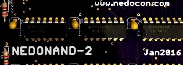
Every few years, someone on the Internet builds a truly homebrew CPU. Not one built with a 6502, Z80, or a CPU from the 80s, either: one built completely out of 74-series logic chips or discrete transistor. We’re lucky enough to have [Alexander] document his build on Hackaday.io, and even luckier to have him enter it into this year’s Hackaday Prize. It’s an 8-bit computer built completely out of NAND gates.

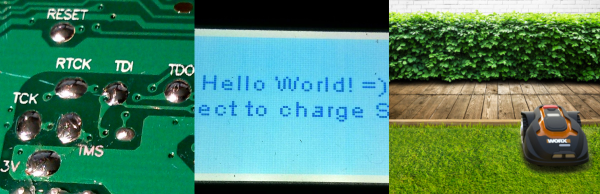
Computers are just logic, and with enough NAND gates, you can do anything. That’s exactly what [Alex] is doing with this computer. It’s built entirely out of 74F00 chips – a ‘fast’ version of the ubiquitous quad 2-input NAND chip. The architecture of this computer borrows from the best CPUs of the 70s and 80s. The ALU is only four bits, like the Z80, but also uses the 6502 technique where the borrow is an inverted carry. It’s a small instruction set, a 2-stage pipeline, and should be able to compute one million instructions per second.

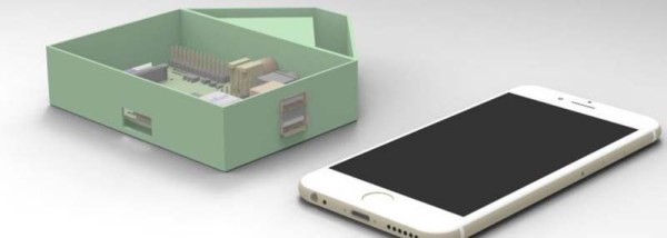
Designing a CPU is one thing, and thanks to Logisim, this is already done. Constructing a CPU is another matter entirely. For this, [Alex] is going for a module and backplane approach, where the ALU is constructed of a few identical modules tied together into a gigantic motherboard. [Alex] isn’t stopping at a CPU, either: he has a 16-byte ROM that’s programmed by plugging diodes into holes.

It’s an amazingly ambitious project, and for entering this project into the 2016 Hackaday Prize, [Alex] already netted himself $1000 and a trip to the final round of competition.

The HackadayPrize2016 is Sponsored by:

Hackaday Prize Entry: A Programmable Calculator With Nixie Tubes

For [Robert]’s entry into The Hackaday Prize, he’s starting off with some basic questions. What’s better than a Nixie tube? More Nixies. What’s better than a calculator? An RPN calculator. What do you get when you combine the two? A calculator that is absurdly large, even by 1970s desk calculator standards, uses a lot of power, and takes up too much space. Sounds good to us.

Nixies, at least when there are a lot of them, are tricky devices. They only draw about 50mA of current, but they only light up when above 150V. That’s only about seven watts, and it’s easy enough for the Arduino-heads out there to build a circuit to drive a few Nixies for a clock. Driving dozens of Nixies is a bit harder. For [Robert]’s RPN calculator, he’s estimating a little under 50W of power being dumped into this calculator.

With the considerable power considerations taken care of, [Robert] turned his attention to the display board. This is going to be a very impressive build, with 80 IN-12B tubes organized in four stack levels of twenty tubes each. The tubes will be controlled with the Maxim MAX6922 VFD driver. This chip has a serial interface, which means it’s relatively easy to have any microcontroller blink these tubes. And of course, it does double-duty as a clock.

The HackadayPrize2016 is Sponsored by:

Hackaday Prize Entry: A Cheaper Soldering Solution

Everyone goes through a few phases during their exploration of electrons, and nowhere is this more apparent than the choice of soldering iron. The My First Soldering Iron™ is an iron that plugs directly into the wall, and doesn’t have temperature control. They’re cheap, and electronics isn’t for everyone, giving the quitters the opportunity to take up woodburning as a hobby. The next step up is a temperature controlled iron, probably an Aoyue or Hakko. The best soldering iron? You’re looking at a Metcal or Weller, and your wallet will become a few hundred dollars lighter.

Your My First Soldering Iron™ need not be terrible, though. For his project for The Hackaday Prize, [HP] is working on a soldering iron that is cheap, accurate, and uses the very nice Weller RT tips. No, it’s not as good as a Metcal or proper Weller, but it’s good enough for some fine soldering work and will give the Aoyues and Hakkos a run for their money.

If price is a reasonable measure of the quality of a soldering iron, the irons that use these Weller RT tips are the best irons around. The tips, though, are pretty cheap: about $30, which gets you a heater and thermistor and not much else. There have been numerous reverse engineering efforts for this iron ([1] and [2]), and even a few Arduino-based circuits that replicate the functionality of the Weller base unit.

[HP] is going in a different direction to heat these iron tips. Instead of building a big box to hold the electronics, he’s building everything into the handle of the soldering iron. With brains donated from an ATMega168, a few op-amps, MOSFETS, and a single power jack, [HP] can heat up this soldering iron tip in a compact, hand-held unit.

For his Hackaday Prize entry, [HP] did a rundown of soldering pen in a video. You can check that out below.

Continue reading “Hackaday Prize Entry: A Cheaper Soldering Solution”

Hackaday Prize Entry: Optical Experiments Using Low Cost Lasercut Parts

Experimenting with optics can be great fun and educational. Trouble is, a lot of optical components are expensive. And other support paraphernalia such as optical benches, breadboards, and rails add to the cost. [Peter Walsh] and his team are working on designing a range of low-cost, easy to build, laser cut optics bench components. These are designed to be built using commonly available materials and tools and can be used as low-cost teaching tools for high-schools, home experimenters and hacker spaces.

They have designed several types of holders for mounting parts such as lasers, lenses, slits, glass slides, cuvettes and mirrors. The holder parts are cut from ¼ inch acrylic and designed to snap fit together, making assembly easy. The holders consist of two parts. One is a circular disk with three embedded neodymium magnets, which holds the optical part. The other is the base which has three adjustment screws which let you align the optical part. The magnets allow the circular disk to snap on to the screws on the base.

A scope for improvement here would be to use ball plunger screws instead of the regular ones. The point contact between the spherical ball at the end of the screw and the magnet can offer improved alignment. A heavy, solid table with a ferrous surface such as a thick sheet of steel can be used as a bench / breadboard. Laser cut alignment rods, with embedded magnets let you set up the various parts for your experiment. There’s a Wiki where they will be documenting the various experiments that can be performed with this set. And the source files for building the parts are available from the GitHub repository.

Check out the two videos below to see how the system works.

Continue reading “Hackaday Prize Entry: Optical Experiments Using Low Cost Lasercut Parts”

Clever And Elegant Tilt Sensors From Ferrofluid

Let’s talk about tilt sensors for a second. The simplest tilt sensors – the dead simplest – are a few ball bearings rolling around in a small metal can. When the can is tilted, the balls roll into a pair of electrical contacts, completing the circuit. How about a drop of mercury in a glass ampule with a few contacts? Same thing. You can get more expensive tilt sensors, including a few that are basically MEMS gyros, but they’re all pretty much the same. For [Aron]’s project for the Hackaday Prize, he’s come up with a tilt sensor that is so clever, so innovative, and so elegant, we’re gobsmacked by his creativity.

5700111461442877186Instead of electrical contacts or gyroscopes, [Aron] is using induction to measure the tilt of a sensor. By wrapping a tube with one long primary winding of copper wire, and several secondary windings in various places, [Aron] built a Linear Variable Differential Transformer. If you insert an iron rod inside this transformer, different voltages will be induced in the primary. Simple, and this device is effectively a position sensor for any ferrous material.

Now for the real trick: put ferrofluid in the core of that transformer. Liquids always find their level, and different tilts will induce different voltages in the primary. Brilliant. Continue reading “Clever And Elegant Tilt Sensors From Ferrofluid”

Reverse Engineer Your Robot Lawnmower

Your home is your castle, and you are king or queen of all you survey. You’ve built your own home-automation system from scratch. Why would you possibly settle for the stock firmware in your robotic lawnmower? [Daniel Wiegert] wouldn’t either, so in Project Landlord he has started to reverse-engineer it.

You can hardly blame him. The Worx Landroid‘s controller board uses an NXP LPC1768 ARM Cortex-M3, and the debug pins are labelled on the backside. The manufacturer didn’t protect the flash memory. It’s just begging to have its firmware dumped. So far, [Daniel] has managed to both brick and unbrick the device, and has completely mapped the controller’s pinout, so he’s on his way to complete control.

Right now, he’s got a working proof-of-concept firmware on his GitHub that’s able to drive the machine around a little bit and set the brakes. It’s running FreeRTOS, and [Daniel] is looking for other people to get in on the project. He’s done the hard initial work, so get in there and reap the rewards! Just don’t neglect to remove the blade before custom firmware.

Will custom firmware in a robotic lawnmower change the world? Probably not. But it is awesome, and will certainly make a difference in the lives of people whose robot mowers continually get stuck behind the hydrangeas.

The HackadayPrize2016 is Sponsored by:

An Open Source Lead Tester

If you’ve ever needed an example of colossal failure of government actors, you need only to look at Flint, Michigan’s water crisis. After the city of Flint changed water supplies from Detroit to the Flint river, city officials failed to add the correct corrosion inhibitors. This meant that lead dissolved into the water, thousands of children were exposed to lead in drinking water, a government coverup ensued, [Erin Brockovich] showed up, the foreman of the Flint water plant was found dead, and the City Hall office containing the water records was broken into.

Perhaps inspired by Flint, [Matthew] is working on an Open Source Lead Tester for his entry into the 2016 Hackaday Prize.

[Matthew]’s lead tester doesn’t test the water directly. Instead, it uses a photodiode and RGB LED to look at the color of a lead test strip. These results are recorded, and with a bit of a software backend, an entire city can be mapped for lead contamination in a few days with just a few of these devices.

One problem [Matthew] has run into is the fact the Pi does not have analog to digital conversion, making reading a photodiode a little harder than just plugging a single part into a pin header and watching an analog value rise and fall. That really shouldn’t be a problem – ADCs are cheap, especially if you only need a single channel of analog input with low resolution. [Matthew] is also looking into using the Pi webcam for measuring the lead test strip. There are a lot of decisions to make, but any functional device that comes out of this project will be very useful in normal, functioning governments. And hopefully in Flint, Michigan too.

The HackadayPrize2016 is Sponsored by: