Satisfy Your High-Voltage Urges With This Printable Flyback Transformer

Sick of raiding old TVs and CRT monitors for flyback transformers to feed your high-voltage addiction? Never fear; if you’re careful, a 3D-printed flyback might be just the thing you’re looking for.

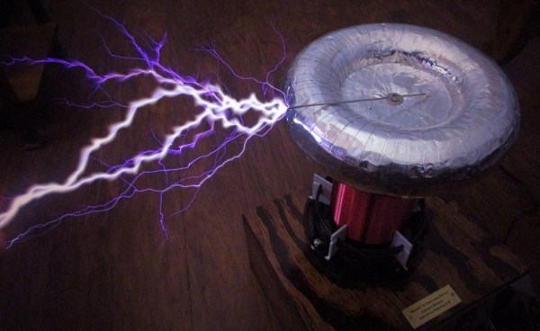
To be fair, it’s pretty easy to come by new flyback transformers, so building your own isn’t strictly necessary. But [SciTubeHD] was in the market for a particularly large flyback, in a good-natured effort to displace [Jay Bowles] from his lofty perch atop the flyback heap. And it’s also true that this project isn’t entirely 3D-printed, as the split core of the transformer was sourced commercially. The secondary coil, though, was where most of the effort went, with a secondary form made from multiple snap-together discs epoxied together for good measure. The secondary has about a kilometer of 30-gauge magnet wire while the primary holds just ten turns of 8-gauge wire covered with silicone high-voltage insulation.

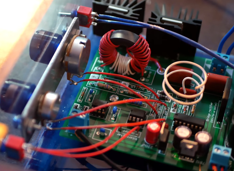
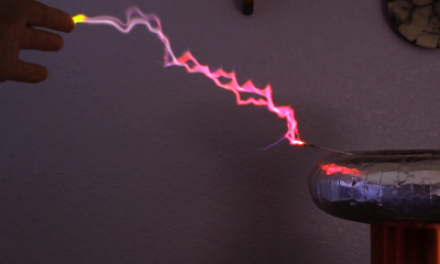
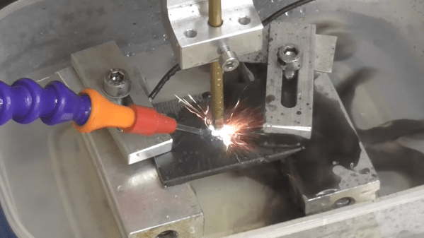
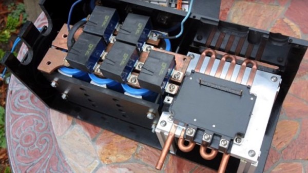
To decrease the likelihood of arcing, the transformer was placed in a plastic container filled with enough mineral oil liquid dielectric to cover the secondary. After degassing in a vacuum chamber for a day, [SciTubeHD] hooked the primary to a couple of different but equally formidable-looking full-bridge inverters for testing. The coil was capable of some pretty spicy arcs — [SciTubeHD] measured 20 amps draw at 35 volts AC input, so this thing isn’t to be trifled with. STL files for the core parts are coming up soon; we trust schematics for the power supply will be available, too.

Continue reading “Satisfy Your High-Voltage Urges With This Printable Flyback Transformer”

Lies, Damned Lies, And IGBT Datasheets

We have all seen optimistic claims for electronic products that fail to match the reality, and [Electronic Wizard] is following one up in a recent video. Can a relatively small IGBT really switch 200 A as claimed by a dubious seller? Off to the datasheet to find out!

The device in question is from Toshiba, and comes in a TO-220 package. This itself makes us pause for a minute, because we suspect the pins on a TO220 would act more like fuses at a steady 200 A.

But in the datasheet, there it is: 200 A. Which would be great, but of course it turns out that this is the instantaneous maximum current for a few microsecond pulse. Even then it’s not finished, because while the continuous current is supposed to he half that, in the datasheet it specifies a junction temperature of 25 °C. The cooling rig required to maintain that with this transistor passing 200 A would we think be a sight to behold, so for all intents and purposes this can’t even switch a continuous 100 A. And the real figure is much less as you’d imagine, but it raises an important point. We blindly read datasheets and trust them, but sometimes we should engage brain before releasing the magic smoke.

Continue reading “Lies, Damned Lies, And IGBT Datasheets”

High Tech Pancake Tesla Coil Brings The Lightning

For several years now we’ve been following [Jay Bowles] as he brings high-voltage down to Earth on his Plasma Channel YouTube channel. From spark gaps made of bits of copper pipe to automotive ignition coils driven by the stalwart 555 timer, he’s got a real knack for keeping his builds affordable and approachable. But once in a while you’ve got to step out of your comfort zone, and although the dedicated DIY’er could still replicate the solid state “pancake” Tesla coil he documents in his latest video, we’d say this one is better left for the professionals.

The story starts about nine months ago, when [Jay] was approached by fellow YouTuber [LabCoatz] to collaborate on a PCB design for a solid state Tesla coil (SSTC). Rather than a traditional spark gap, a SSTC uses insulated-gate bipolar transistors (IGBTs) triggered by an oscillator, which is not only more efficient but allows for fine control of the primary coil. The idea was to develop an AC-powered coil that was compact, easy to repair, and could be controlled with just a couple dials on the front panel. The device would also make use of an antenna feedback system that would pick up the resonant frequency of the secondary coil and automatically adjust the IGBT drive to match.

Being considerably more complex than many of the previous builds featured on Plasma Channel, it took some time to work out all the kinks. In fact, the majority of the video is [Jay] walking the viewer through the various failure modes that he ran into while developing the SSTC. Even for somebody with his experience in high-voltage, there were a number of headscratchers that had to be solved.

For example, the first version of the design used metal bolts to attach the primary and secondary coils, until he realized that was leading to capacitive coupling and replaced them with acrylic blocks instead. If his previous videos surprised you by showing how easy it could be to experiment with high-voltages, this one is a reminder that it’s not always so simple.

But in the end [Jay] does get everything sorted out, and the results are nothing short of spectacular. Even on the lower power levels it throws some impressive sparks, but when cranked up to max, it offers some of the most impressive visuals we’ve seen so far from Plasma Channel. It was a lot of work, but it certainly wasn’t wasted effort.

Fascinated by the results, but not quite ready to jump into the deep end? This affordable and easy to build high-voltage generator featured on Plasma Channel back in 2020 is a great way to get started. If you still need more inspiration, check out the fantastic presentation [Jay] gave during the 2021 Remoticon.

Continue reading “High Tech Pancake Tesla Coil Brings The Lightning”

A Builders Guide For The Perfect Solid-State Tesla Coil

[Zach Armstrong] presents for your viewing pleasure a simple guide to building a solid-state Tesla coil. The design is based around a self-resonant setup using the UCC2742x gate driver IC, which is used in a transformer-coupled full-wave configuration for delivering maximum power from the line input. The self-resonant bit is implemented by using a small antenna nearby the coil to pick up the EM field, and by suitably clamping and squaring it up, it is fed back into the gate driver to close the feedback loop. Such a setup within reason allows the circuit to oscillate with a wide range of Tesla coil designs, and track any small changes, minimizing the need for fiddly manual tuning that is the usual path you follow building these things.

Since the primary is driven with IGBTs, bigger is better. If the coil is too small, the resonant frequency would surpass the recommended 400 kHz, which could damage the IGBTs since they can’t switch much faster with the relatively large currents needed. An important part of designing Tesla coil driver circuits is matching the primary coil to the driver. You could do worse than checkout JavaTC to help with the calculations, as this is an area of the design where mistakes often result in destructive failure. The secondary coil design is simpler, where a little experimentation is needed to get the appropriate degree of coil coupling. Too much coupling is unhelpful, as you’ll just get breakdown between the two sides. Too little coupling and efficiency is compromised. This is why you often see a Tesla coil with a sizeable gap between the primary and secondary coils. There is a science to this magic!

Pretty Lithium Carbonate plasma

A 555 timer wired to produce adjustable pulses feeds into the driver enable to allow easily changing the discharge properties. This enables it to produce discharges that look a bit like a Van De Graaff discharge at one extreme, and produce some lovely plasma ‘fire’ at the other.

We’ve covered Tesla coils from many angles over the years, recently this plasma tweeter made sweet sounds, and somehow we missed an insanely dangerous Tesla build by [StyroPyro] just checkout that rotary spark gap – from a distance.

Continue reading “A Builders Guide For The Perfect Solid-State Tesla Coil”

Homemade EDM Machine Moves From Prototype To Production

Of all the methods of making big pieces of metal into smaller pieces of metal, perhaps none is more interesting than electrical discharge machining. EDM is also notoriously fussy, what with having to control an arc discharge while precisely positioning the tool relative to the workpiece. Still, some home gamers give it a whirl, and we love to share their successes, like this work-in-progress EDM machine. (Video, embedded below.)

We’ve linked [Andy]’s first videos below the break, and we’d expect there will be a few more before all is said and done. But really, for being fairly early in the project, [Andy] has made a lot of progress. EDM is basically using an electric arc to remove material from a workpiece, but as anyone who has unintentionally performed EDM on, say, a screwdriver by shorting it across the terminals in a live outlet box, the process needs to be controlled to be useful.

Part 1 shows the start of the build using an old tap burning machine, a 60-volt power supply, and a simple pulse generator. This was enough to experiment with the basics of both the mechanical control of electrode positioning, and the electrical aspects of getting a sustained, useful discharge. Part 2 continues with refinements that led very quickly to the first useful parts, machined quickly and cleanly from thin stock using a custom tool. We’ll admit to being impressed — many EDM builds either never get to the point of making simple holes, or stop when progressing beyond that initial success proves daunting. Of course, when [Andy] drops the fact that he made the buttons for the control panel on his homemade injection molding machine, one gets the feeling that anything is possible.

We’re looking forward to more on this build. We’ve seen a few EDM builds before, but none with this much potential.

Continue reading “Homemade EDM Machine Moves From Prototype To Production”

An EV Motor Controller Home Build

Many of us will have experimented with brushless motors, and some of us will have built our own controllers rather than using an off-the-shelf part. Doing so is a good way to understand their operation, and thus to design better brushless motor powered projects. Few of us will have gone as far as [etischer] though, and embarked upon building our own controller for a 300V 90kW traction motor.

The tricky part of a high power brushless motor controller lies not in the drive but in the high-power switching arrangements. He’s using a bank of IGBTs, and to drive them he’s using a smaller industrial variable frequency drive controller with its own output transistors removed. He takes us through some of the development of the system, including showing him blowing up a set of IGBTs through having too much inductance between transistors and reservoir capacitor, and then to his final design.

This is part of a project VW first converted ten years ago, and as part of a series of videos he’s produced one going through the whole project. It’s a fascinating breakdown of the parts required for an EV conversion, and the teething troubles he’s encountered along the way.

Continue reading “An EV Motor Controller Home Build”

Improbably Cheap Pocket Welder Gets An ESP32 Makeover

If you move in certain shady circles, you may have noticed the crop of improbably cheap “pocket welders” popping up on the market these days. They’re all variations on a theme, most with wildly optimistic specs minimal accessories of the lowest possible quality. But their tiny size and matching price make them irresistible to the would-be welder, as well as attractive to hardware hackers.

With a 220-V outlet in the garage waiting to be filled and well-knowing the risks, [Mr. RC-Cam] purchased one of these diminutive welding machines. Its shortcomings were immediately apparent, and a complete rework of the welder was undertaken. After addressing safety issues like the lack of a ground connection, [Mr. RC-Cam] added a color-matched 3D-printed hood to house a fancy new LCD touchscreen display. Backing that up is an ESP32 with Bluetooth, which supports remote control via a key fob. He also added a current sense board that uses the welder’s current shunt to measure welding current. Expediently calibrated using a waffle iron and a milli-ohmmeter, the sensor showed that the 200A max advertised for the welder was more like 100A. He tried adding some big electrolytics to fix the current issues, but no dice. With a decent stinger and ground clamp, the modified welder is good enough for his needs, and much was learned in the process. We call that a hacking win.

As an aside, [This Old Tony] recently did a review on a similar welder if you want more details on the internals. We also covered the conversion of a buzz-box to a TIG welder recently, should that be more your style.

Continue reading “Improbably Cheap Pocket Welder Gets An ESP32 Makeover”