You can say one thing for [Derek]’s amateur radio ambitions — he certainly jumps in with both feet. While most hams never even attempt to “shoot the Moon”, he’s building out an Earth-Moon-Earth, or EME, setup which requires this little beauty: a homebrew quarter-wave hardline RF divider, and he’s sharing the build with us.
For background, EME is a propagation technique using our natural satellite as a passive communications satellite. Powerful, directional signals can bounce off the Moon and back down to Earth, potentially putting your signal in range of anyone who has a view of the Moon at that moment. The loss over the approximately 770,000-km path length is substantial, enough so that receiving stations generally use arrays of high-gain Yagi antennas.
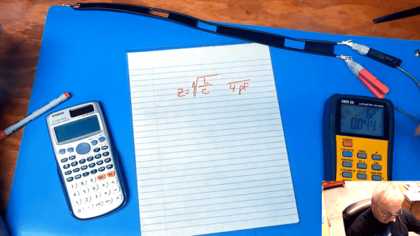
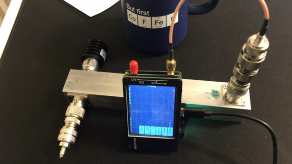
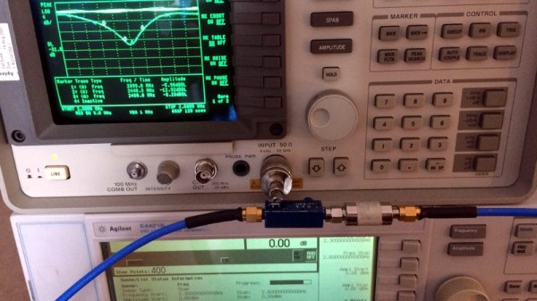
That’s where [Derek]’s hardline build comes in. The divider acts as an impedance transformer and matches two 50-ohm antennas in parallel with the 50-ohm load expected by the transceiver. He built his from extruded aluminum tubing as the outer shield, with a center conductor of brass tubing and air dielectric. He walks through all the calculations; stock size tubing was good enough to get into the ballpark for the correct impedance over a quarter-wavelength section of hardline at the desired 432-MHz, which is in the middle of the 70-cm amateur band. Sadly, though, a scan of the finished product with a NanoVNA revealed that the divider is resonant much further up the band, for reasons unknown.
[Derek] is still diagnosing, and we’ll be keen to see what he comes up with, but for now, at least we’ve learned a bit about homebrew hardlines and EME. Want a bit more information on Moon bounce? We’ve got you covered.
Continue reading “Shoot The Moon With This Homebrew Hardline RF Divider” →