Look through the last two decades of electronics project built on perfboard, and you’ll notice a trend. Perfboard is designed for through-hole parts, but ever more frequently, the parts we need are only available as surface mount devices. What does this mean for the future of all those protoboard, veroboard, and tagboard designs? It’s not good, but fortunately, there may be an answer. It’s perfboard designed for mounting SOICs, SOTs, and other surface mount devices.
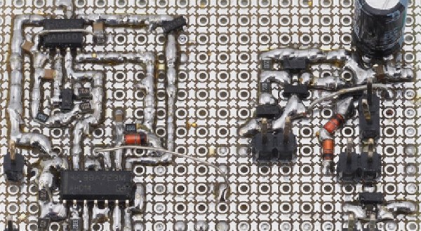
Perfboard is an extremely simple concept. Most through-hole electronic components are built around 0.1″ or 2.54 mm spacing between pins. Yes, there are exceptions, but you can always bend the middle pin of a transistor and put it in a hole. SMT devices are different. You can’t really bend the pins, and the pin pitch is too small for the 0.1″ holes in traditional perfboard.
[electronic_eel] is changing that game up with his own design for perfboard. This perfboard has the traditional 0.1″ holes, but there are SMD pads sprinkled about between these holes. The result is being able to solder SOIC, SOT23-6, SOT23 and SOT363 devices directly to a board alongside 0603 and 0805 devices. Connect everything with a few beads of solder and you have a functional circuit made out of surface mount devices on something that’s still compatible with the old protoboard designs.
This isn’t the first time we’ve seen a new type of protoboard make it into production. A few years ago, Perf+, a bizarre ‘bus-based’ protoboard solution came onto the scene, although that wasn’t really designed for SMD parts. While [electronic_eel] doesn’t have any plans to sell his protoboard, the files are available, and you can easily design your own small piece of perfboard.


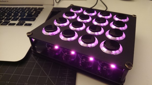
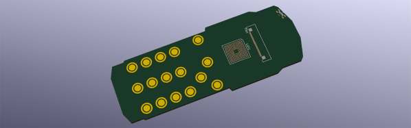


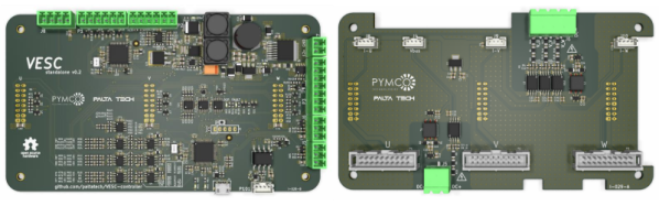
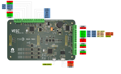 While [Vedder]’s controller is aimed at low power applications such as skate board motors, [Marcos]’s version amps it up several notches. It uses 600 V 600 A IGBT modules and 460 A current sensors capable of powering BLDC motors up to 150 kW. Since the control logic is seperated from the gate drivers and IGBT’s, it’s possible to adapt it for high power applications. All design files are available on the


