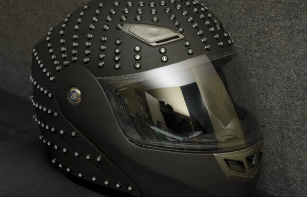
Writing On LEDs With A Laser Pointer

After [Ch00f] got his hands on an 8×8 LED display, he didn’t make a 64-pixel video game or VU meter. He made a laser doodler, allowing him to draw on this display with only a laser pointer.

Using LEDs as light sensors is nothing new; [Forrest Mims III] discovered that LEDs can also detect light way back in the late 60s. [Ch00f] played around with this concept before creating a circuit that uses an LED as both a light emitter and sensor that reacts to the ambient brightness.

[Ch00f]’s laser doodler takes this phenomena and applies it to an Adafruit bicolor LED matrix. When a light shines on an individual pixel in the display, the ATMega48 senses the current and turns that pixel on. Since this these pixels have two colors, [Ch00f] used a latch circuit and a button to cycle between what color the ‘Mega writes to the display.

In the video after the break, [Ch00f] shows off his display by having the LEDs light up in response to a laser pointer. It may be a bit small, but we can see a lot of potential for something like this as a gigantic art installation.

Continue reading “Writing On LEDs With A Laser Pointer”

The Many Iterations Of [Joe’s] PCB Business Card

[Joe Colosimo] is putting on a show with his PCB business card project. The idea isn’t new, but his goal is to keep it simple and undercut the cost of all other PCB cards he’s seen. This is the third generation of the board design, and he’s just waiting on some solder mask solution before he tries running it through the reflow oven.

The first two prototypes used some through-hole parts. Notably, the battery was to be positioned in a circular cut-out and held in place by a metal strap and some bare wires. But he couldn’t quite get it to work right so this design will transition to a surface-mount strap for one side, and the large circular pad for the other. At each corner of the board there is a footprint for an LED. He tried milling holes in the board to edge-light the substrate. Now he just mounts the LED upside down to give the board a blue glow. The LEDs are driven by an ATtiny10 microcontroller which takes input from the touch sensor array at the bottom right.

He etched a QR code on the board which seems to work better than the milled QR experiments we saw back in April. The link at the top point’s to [Joe’s] main page on the card. Don’t forget to follow the links at the bottom which cover each part of the development more in-depth.

[Thanks Skitchin]

Fabricating Headlights For An F250

The amount of time that is going into these custom headlights is just staggering. [Mcole254] is working on his brother’s truck, replacing the stock headlights with High-Intensity Discharge (HID) lamps and rolling some nice LED features into the mix while he’s at it.

The build starts by removing and disassembling the stock headlight assembly. In order to get the enclosure apart he heated it in the oven until the glue was softened and the parts could be pried apart. The goal is to replace the reflectors with an assembly that suits the new lamps and LEDs. Above you can see the white pieces which were vacuum formed from a mold that [Mcole254] made from wood and PVC. He tried several iterations using his home-made vacuum former but couldn’t get the definition he really wanted. The most recent posts from him show some massive 3D printed parts that will be used instead.

While inside he added a line of amber LEDs for the turn signal. You can seem them mounted along the silver strip between the upper and lower reflectors. A demo of those super bright additions is embedded after the break.

Continue reading “Fabricating Headlights For An F250”

Levitating Lightbulb Does It All With No Wires

It would be really fun to do an entire hallway of these levitating wireless lights. This a project on which [Chris Rieger] has been working for about six months. It uses magnetic levitation and wireless power transfer to create a really neat LED oddity.

Levitation is managed by a permanent magnet on the light assembly and an electromagnetic coil hidden on the other side of the top panel for the enclosure. That coil uses 300 meters of 20 AWG wire. A hall effect sensor is used to provide feedback on the location of the light unit, allowing the current going to the coil to be adjusted in order to keep the light unit stationary. When working correctly this draws about 0.25A at 12V.

Wireless power transfer is facilitated by a single large hoop of wire driven with alternating current at 1 MHz. This part of the system pulls 0.5A at 12V, bringing the whole of the consumption in at around 9 Watts. Not too bad. Check out [Chris’] demo video embedded after the break.

A similar method of coupling levitation with power transfer was used to make this floating globe rotate.

Continue reading “Levitating Lightbulb Does It All With No Wires”

Computer Desk… Literally

This piece of furniture begs the question, why think of a desk and a computer case as separate things? It combines Ikea furniture with electronic hardware to create the ultimate command center.

First the obvious parts: there’s a nook for the computer case that hangs just below the desktop off to the side, and the twin displays are mounted front and center. The divider between the cabinet pieces was cut away to allow the monitors to be wall-mounted. But things start to get interesting to the left of those monitors. You can see a series of dial displays in the door for that cabinet. Those meters were sourced from the MIT Flea Market and after a bit of alteration they display CPU load information fed to them by  an Arduino board. This also drives some LED strips which are mounted behind the frosted glass panel that we guess could be called a back splash. The heavier the load, the better the light show.

All of the power management is taken care of in the cabinet to the right of the monitors. The top row hides a printer, external hard drive backup system, and several gaming consoles. Heat will be an issue so exhaust fans were added to each of these partitions. They’re switched based on a temperature sensor in each. It’s a lot of work, but the outcome proves it was worth it.

[via Reddit]

Blinky Headgear

This hat has a chasing LED feature thanks to our old friend the 555 timer. [BananaSlug] even built in the option to change the speed at the push of a button.

His design starts out with a costume hat. Each of the 25 LEDs is soldered to a 2×4 hole chunk of protoboard. The LED package is pushed through a slit in the hat, but the protoboard remains on the inside where it can be sewn in place. From there [BananaSlug] soldered one negative bus around the circumference, and an individual positive lead from each module back to the control board. They’re addressed by a set of CD4017 decade counters which are clocked by the 555 timer circuit.

This is a great little analog/logic project and the style is perfect if you’ve got the coat to go along with it.

Revolight Clone

[Fabian.E] wanted to light up the rims on his bike, but didn’t want to shell out a bunch of clams to get it done. He came up with this system which uses magnets and reed switches to light up one arc or each bicycle wheel.

He calls it the lightrider and it’s based on the revolights concept. That design uses a microcontroller which is capable of animating patterns when the wheels aren’t spinning. [Fabian’s] version can’t do that, but the effect while moving is basically the same. The ring of LEDs around the rim is connected to a battery via a set of reed switches. When these switches move past a magnet on the fork it completes the circuit and switches on that segment of LEDs. The clip after the break gives a demonstration of the finished product, and includes a fast-motion video of the fabrication process.

Continue reading “Revolight Clone”