Color Sensor Gives The RGB Values Of Anything

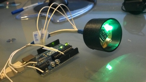
[Rick Osgood] wanted to build a color sensor that could be held up to any object to get RGB color values. He originally started with a photoresistor and a few LEDs, but couldn’t get that to work reliably. [Rick] finally completed his color sensor after finding a digital luminosity sensor on Adafruit, ending up with a pretty accurate piece of hardware to judge the color of something.

The idea behind the color sensor is to light up red, green, and blue LEDs and see how much light is reflected back from the object with a luminosity sensor. [Rick] chose an Arduino to do all the heavy lifting for the light sensor and activating the LEDs.

After a few tests [Rick] got his color sensor working, but it’s not up to par with what he had expected. This isn’t really a problem: the LEDs probably don’t have the same brightness and the luminosity sensor doesn’t respond evenly across the entire rainbow. Those things can always be fixed in software, though. It’s a nice project that could serve as part of a prototype for this color picker pen.
office-game-show-buzzer

Office Game Show Buzzer Keeps Things Fair And Square

The sales team in [Chuck’s] office is a pretty competitive bunch as you might expect, and they decided that they wanted a system which would allow them to challenge one another during their weekly meetings. The competition involves answering questions posed by their manager, but hand raising only works for so long – they needed a definitive way to tell who “buzzed in” to answer a question first.

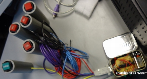
Since [Chuck] only had a short bit of time and a tiny budget to work on, he opted to find the easiest solution to the problem, which was an Arduino-based game show buzzer system. The game display is built from an Arduino, some LEDs and an Altoids tin, while the buzzer pushbuttons were salvaged from an old radio broadcast console.

Now, when a question is posed, the salesman can buzz in to answer, knowing that only the quickest person’s button click will be registered. When it’s time for another question, the host simply clicks his buzzer to reset the console.

While it’s not quite as fancy as this game buzzer system we featured a while back, [Chuck] says it does the job perfectly and was cheap to boot.

Continue reading to see a short video of the office game buzzer system in action.

Continue reading “Office Game Show Buzzer Keeps Things Fair And Square”

Paint Your Pictures, No PC Needed

LEDs and and cameras always make a fun mixture, and its not all that hard to have quite a bit of fun as well. The Light Painting Stick is similar to other long exposure camera tricks like LightScythe and gets about the same reults. The difference is the Light Painting Stick is self contained meaning you don’t have to drag nearly as much stuff along with you to have fun.

Hardware used is HL1606 controlled RGB led strip commonly found at Adafruit, the brains are a Leaf Labs Maple micro controller board with an SD card and some human interfaces attached, and is powered by a 6 volt lantern battery.

Images are 64*infinity 24 bit BMP files which means there is not much fuss preparing your graphics other than doing a simple rotate. You can select which image is displayed by using a 2 way switch and the LEDs on the stick. Select your images, dial in your speed with the potentiometer, and you’re  ready to hit the fire button for some photo fun.

Very Accurate Clock Can’t Be Read Accurately

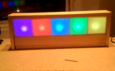
[Martijn] is showing off his new clock which he calls a Light Spectrum Clock. We like to look of it, using RGB LEDs in five squares that remind us of some of those LED coffee table builds. From left to right this shows the week, day, hour, minute, and second. Simple, right?

We had to smile a little bit when looking through his write up. He chose an Arduino nano as a controller, using a TLC5940 chip to drive the LEDs. But it is the inclusion of a DS1307 real-time clock that we find amusing. It will keep quite accurate time (not quite as well as the DS3232 but still respectable) but the fuzzy display technique makes telling the time accurately an impossibility. But like other color-based clocks, that’s part of the fun. The real reason for using an RTC chip is that they usually include battery-backed operation so that you can shut off the LEDs when you’re not around and the clock will continue to tick.

You can watch the seconds pass by as fading colors in the clip after the break.

Continue reading “Very Accurate Clock Can’t Be Read Accurately”

Building A LED Strip The Minimal Way

For his first big build with an MSP430, [Javon] decided to an RGB LED fader. Having worked with Arduinos in the past, he figured that his MSP430 would have a few PWM channels. After being proved wrong by the data sheet, [Javon] needed to figure out a way to switch a bunch of RGB LEDs with only one PWM channel on his microcontroller.

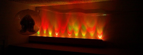
Because there was only one PWM pin on [Javon]’s micro, he needed a way to multiplex his output. He ended up using a 74HC4052 mux/demux chip to drive 20 LEDs. The LEDs were mounted onto hard board and the main part of the circuit built on a bit of perfboard. While there’s no total cost for his build, we’re guessing [Javon] didn’t spend much on his project; certainty much less than this explosion of LEDs.

[Javon] put all the build pictures up as a Google+ album and a few video demos up. Check those out after the break (009 Sound System warning, you might want to hit mute).

Continue reading “Building A LED Strip The Minimal Way”

Fixing The Control Scheme For An Aftermarket Headlight Assembly

The headlight enclosures on [Bill Porter’s] 2004 Passat had yellowed with age and were not outputting the kind of light they should. He decided to replace them with some aftermarket modules that also incorporated LED strips. When they arrived he was surprised at how easy there were to drop into place. But when testing he was certainly not satisfied with how they worked. The day-driving mode used the HID bulbs at full power, where the factory assembly had dimmed them during the day. He set out to alter the electronics to work as he prefers.

Always the mad scientist, [Bill] started off by making a truth table showing how the lights reacted to the various states of the ignition and headlight switches. What he came up with is an AND gate built from a relay and diode. It allows him to have the LEDs on as the running lights (without the HIDs on at all), and leaves the rest of the functionality unaffected.

Rainbow Board Of Many Ping-pong Balls

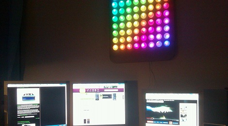
[George] just finished his first project: an 8×8 matrix “Board of Many Ping-Pong Balls” with 64 RGB LEDs. He started this project when he was 14 years old and finished the build over this last Christmas break. We won’t make any presumptions about [George]’s age, but we couldn’t think of a better project to start out on.

For the build, [George] used a Colorduino LED driver shield for his Arduino. This made the wiring simple, but the finished product is where this project really shines. For the base, [George] got a board laser cut at his school and used ping-pong balls to diffuse the LEDs. We’ve seen this many times but with this build there’s a neat way to drill a hole in a ping-pong ball; simply put the drill into reverse. The friction is enough to open the ball up, and the chips of plastic come outside instead of remaining in.

We’re really impressed with [George] and his winter break project. He’s lucky enough to have access to a laser cutter at school, and from a look at his monitor, he’s reading the right websites. You can check out his demo rainbow pattern after the break.

Continue reading “Rainbow Board Of Many Ping-pong Balls”