Imagine if you had some magic glowing beads, that would emit beautiful colors without any wires tangling them up. They exist, in the form of wireless induction-powered LEDs, and [Debra] of Geek Mom Projects has been experimenting with them in a new way.
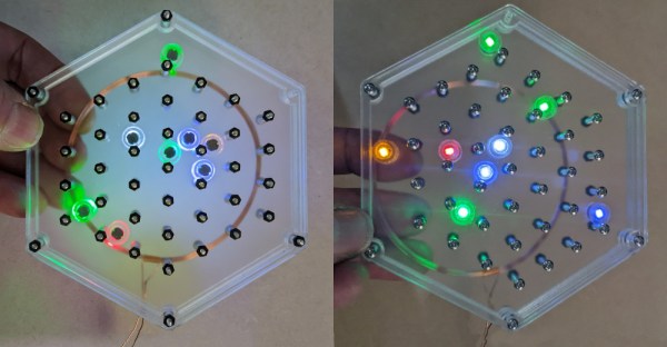
The build takes the wireless LEDs and wraps each one up in a 1/4″-thick clear ring of acrylic. This toughens up the LEDs and helps diffuse their light. They’re then installed in a hexagonal plastic container, featuring a grid of screws not unlike the metal pins of the game Plinko. Thanks to the induction coil mounted behind, the LEDs glow as they ricochet around the metal pins in various ways.
We’d love to see the container full of LEDs mounted on a slowly-turning motor, such that they would tumble around endlessly, glowing all the while. It would be quite mesmerizing, in much the same way as the kaleidoscope project [Debra] built using these parts previously. Video after the break.
Continue reading “Plinko-Like Build Takes Advantage Of Wireless LEDs”