Build Your Own 4-channel Logic Analyzer

If you’re just getting into hobby electronics chances are there are lots of tools you’d like to get you hands on but can’t yet justify the purchases. Why not build some of the simpler ones? Here’s a great example of a 4-channel logic analyzer that can be your next project and will add to your arsenal for future endeavors.

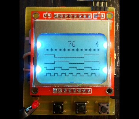
As you can see, [Vassilis’] creation uses a cellphone-sized LCD screen as the output. It is powered by four rechargeable batteries and driven by an ATmega8 microcontroller. He’s designed the tool without power regulation, relying on the ATmega’s rather wide range of operating voltages, and a few diodes to step down that voltage for the LCD screen.

As you can see in the clip after the break, alligator leads can be used to connect the test circuit to the inputs (don’t forget the ground reference!). Thee buttons at the bottom let you navigate the captured data by panning and zooming. Perhaps the best design feature is the single-sided circuit board which should be quite easy to reproduce at home.

Continue reading “Build Your Own 4-channel Logic Analyzer”

Saleae Logic Analyzer Knockoff Hacking

Despite what this module says on the case, it’s certainly not official Saleae Logic Analyzer hardware. [Jack Andrews] picked up this Chinese knockoff on eBay for about $18. When plugged into the computer the Saleae software picks it up as the official hardware. But [Jack] has seen other knockoffs which have a jumper to select between Saleae cloning and USBee cloning so he found a way to switch software with this dongle.

He pulled the board out of the case and discovered a Cypress CY7C68013A microcontroller on a poorly-soldered board (imagine that). This is an 8051-compatible processor that includes USB functionality. There’s also an EEPROM on the bottom of the board which stores the VID/PID pair identifying it as Saleae Logic hardware. The trick to getting this working with the USBee software is to change that pair. [Jack] managed to do this without an external programmer. He uninstalled the Saleae driver and installed a Cypress driver. Then he wrote a bit of code for the CY7C68013A to rewrite the EEPROM and flashed it via the USB connection. Now the dongle enumerates as USBee Logic Analyzer hardware.

Turn A Logic Analyzer Into A Signal Generator Using Only Software

One thing we learned by watching [Alton Brown] on all of those Good Eats episodes is that a multitasker is way better than a unitasker. [Joost] is thinking along the same lines by taking a fantastic tool and adding a useful function to it. His software project turns a USB Saleae Logic Analyzer into a signal generator.

There are already a multitude of reasons to own one of these fantastic tools. But the ability to use it to generate up to 8 channels of PWM signals is a welcome addition. It is capable of producing frequencies from 1Hz up to 1MHz at a sample rate of 4 MHz. It uses the original SDK and doesn’t require any changes to the hardware (we would’ve thought new firmware was necessary, but happily that’s not the case). The one caveat is that right now this only works with Windows machines running the .NET version 3.5 or higher. It looks like an MSI installer package is all that’s available for download so the thoughts of easily porting this to other operating systems have been dashed unless [Joost] decides to share his source code.

Edit 7/12/2016: [Joost]’s webpage is down, but he moved it to Github.

Diving Deep Into The Game Boy LCD Protocol

[Craig] wanted to make the original Game Boy LCD screen do his bidding so he sniffed out the data protocol that it uses. We were amused when he mentions that there’s an army of people out there looking to build pointless crap as part of a hobby. Guilty. And he goes on to outline why this LCD screen is a great resource for hobbiests.

As you can see in the pinout above, it uses 5V logic, with a 4 MHz data clock. These traits are both very friendly to a wide range if inexpensive microcontrollers. If you know how to address the display it should be very easy to use. Furthermore, the low pin count is thanks the to a 4-shade grayscale screen, limiting the data pins to just two. [Craig] hooked up his Saleae Logic probe to capture communications and walks us through what he discovered. During this process he proved to himself that he had figured out the protocol by exporting captured data from the logic probe and reassembling it into an image on his computer.

Open Source Logic Analyzer Software

[Christian Weichel] has been hard at work developing LogicAnalyzer, an open source tool that may interest you. It is designed with SUMP Logic Analyzers in mind but a main goal is expandability. What this means is that it plays nicely with things like the Open Workbench Logic Sniffer or you can do a bit of fiddling to get it to work with your own designs. The program is based on Eclipse so you should be familiar with how it works and you can get it running easily on multiple platforms. Take a look at the wiki for a quick start.

Superprobe

The Superprobe is a logic analyzer, multimeter, and much more rolled into a fun to build project. [Ben Ryves] didn’t come up with the original idea, but he definitely took a good thing and made it better. You can use it to test logic, inject logic into a circuit, read capacitors and resistors, test frequency, read the device address from 1-wire devices, and more. Interchangeable probes, choice of internal or external power, simple two-button operation, and a powerful PIC microcontroller at the heart of it all make this a fantastic tool for your electronics workbench. Check out the quality video after the break that  [Ben] put together to show off the results of his tinkering.

Continue reading “Superprobe”

Four Channel Logic Analyzer

If you’ve got a graphic LCD lying around you can build this four-channel logic analyzer with a couple handfuls of cheap components. [Ronald de Bruijn’s] design uses a PIC18F4580 to sample up to four logic inputs at a maximum resolution of 2 MHz. He’s included the PCB artwork so that you can etch your own board. Having a logic analyzer around can really make your life easier, allowing you to reverse engineer communication protocols and troubleshoot your own design problems.

[Thanks Juan]