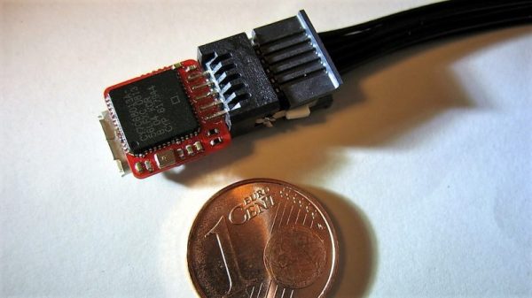
Careful not to sneeze while using this diminutive logic analyzer — you could send it flying across the bench.
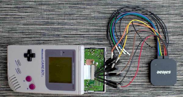
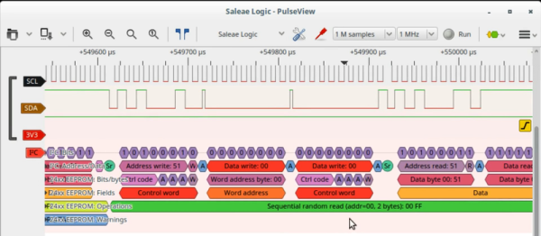
Undertaken more for the challenge than as a practical bench tool, [Uwe Hermann]’s tiny logic analyzer is an object lesson on getting a usable circuit as small as possible. Sure, some sacrifices had to be made; it’s only an eight-channel instrument without any kind of input protection at all, and lacks niceties like an EEPROM. But that allows it to fit on a mere 11 x 11-mm fleck of PCB. That’s a pretty impressive feat of miniaturization, given that the Cypress microcontroller running the show is in QFN package that takes up 64-mm² all by itself. A micro-USB connector takes up much of the back side of the board and allows the analyzer to talk to sigrok, an open-source signal analysis suite.
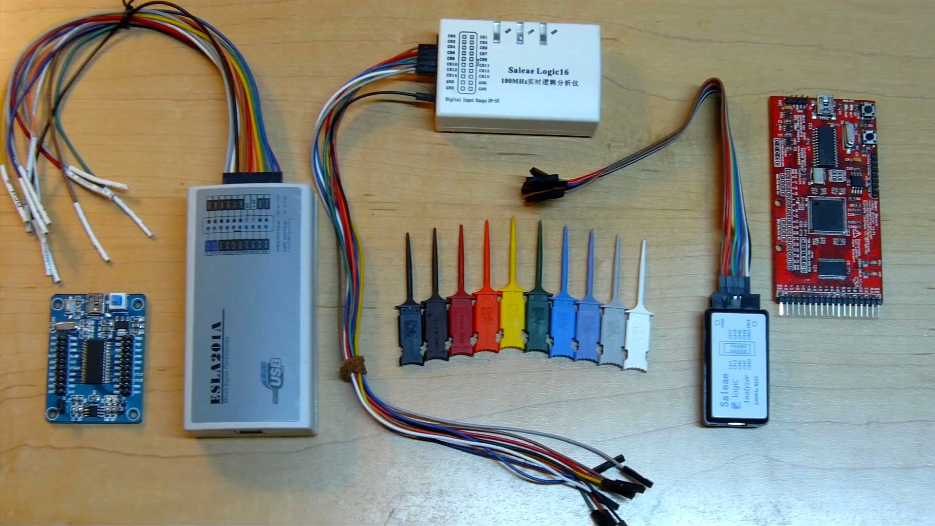
Everything about the project is totally open, including the PCB files, so you can build your own if you feel up to the challenge. We’d strongly suggest you check out this primer on logic analyzers first, though, especially since it focuses on the capabilities of the sigrok suite.