A Number Maze For Younger Hackers

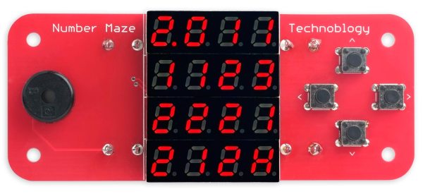
[David Johnson-Davies] has a lofty goal of building a small device to give to younger hackers on a semi-yearly basis. So this last year, he designed and created The Number Maze Game, a small handheld logic puzzle maze.

It’s based on several 4-digit seven-segment displays controlled by an AVR128DA32. Navigation is just a few push buttons and a buzzer to let you know when you’ve won. The game is simple: you jump the amount listed on the space you’re currently on, trying to get to the space labeled “H.” [David] lays out how he built it in great detail, discussing the process of designing and assembly. He also expounds on many decisions, such as using a TQFP microcontroller instead of the through-hole ATmega328P due to the I/O pin count.

The instructions and design process are so detailed we’re confident most people could easily reproduce it, especially with the code and board files. But the value of this project is not in blindly copying it. Instead, we love how something so simple can be wonderfully entertaining and valuable to younger hackers. Programming headers are included so they can add new mazes. We suspect there are many out there who would love to get something so tactile, simple, and modifiable.

Of course, we’ve seen other minimal maze games, so there’s no lack of inspiration for making some different.

Conductive Ink Based On A Simple Idea

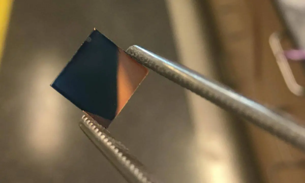
There’s an old series of jokes that starts with: “How do you put an elephant in a refrigerator?” The answer is to open the door, put the elephant inside, and close the door. Most people don’t get that because it is too simple, and simple is the approach Georgia Tech researchers have taken when faced with the problem of using a particular conductive plastic. PEDOT, the plastic in question, is a good conductor, but it is hard to work with. You can add materials to make it easier to work with, but that screws up the conductivity. Their answer is much like the refrigerator joke: add material to PEDOT, paint or print it where you want, and then remove the extra material. Simple.

The polymer needs side chains to be soluble. This allows you to mix an ink or paint made of the material, but the waxy side chains interfere with the material’s conductivity. However, after application, it is possible to break off the side chains and flush them out with a common solvent. The process is simple, and leaves a flexible conductive material that’s stable.

Continue reading “Conductive Ink Based On A Simple Idea”

Illuminated smart curtain in front of a window, beside a Christmas tree

Smart LED Curtain Brings Sprites To Your Windows

Mobile interface for LED smart curtain display
A mobile interface is a nice touch

Anybody who has ever seen a video wall (and who hasn’t?) will be familiar with the idea of making large-scale illuminated images from individual coloured lights. But how many of us have gone the extra mile and fitted such a display in our own homes? [vcch] has done just that with his Deluxe Smart Curtain that can be controlled with a phone or laptop.

The display itself is made up of a series of Neopixel strips, hung in vertical lines in front of the window.  There is a wide gap between each strip, lending a ghostly translucent look to the images and allowing the primary purpose of the window to remain intact.

The brains of the system are hosted on a low-cost M5stack atom ESP32 device. The data lines for the LEDs are wired in a zig-zag up and down pattern from left to right, which the driver software maps to the rectangular images. However, the 5V power is applied to the strips in parallel to avoid voltage drops along the chain.

If you’d like to build your own smart curtain, Arduino sketch files and PHP for the mobile interface are included on the project page. Be sure to check out the brief video of what the neighbors will enjoy at night after the break.

If video walls are your kind of thing, then how about this one that uses Ping Pong Balls as diffusers? Continue reading “Smart LED Curtain Brings Sprites To Your Windows”

Make Your Own Pot And Encoder Knobs, Without Reinventing Them

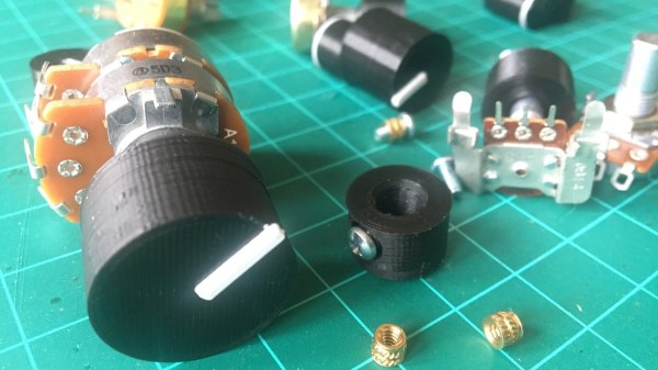
Rotary potentiometers, switches, and encoders all share a basic design: adjustment is done via a shaft onto which a knob is attached, and knobs are sold separately. That doesn’t mean one knob fits all; there are actually a few different standards. But just because knobs are inexpensive and easily obtained doesn’t mean it’s not worth making your own.

A simple and effective indicator can be easily printed in a contrasting color.

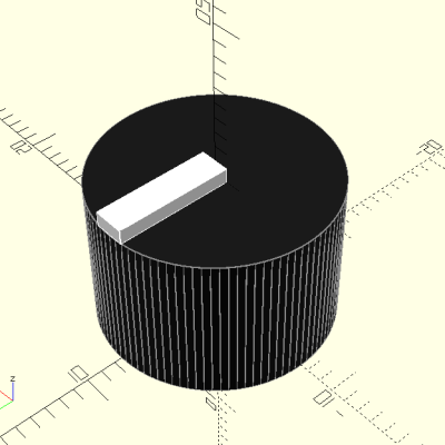
Why bother 3D printing your own knobs instead of buying them? For one thing, making them means one can rest assured that every knob matches aesthetically. The ability to add custom or nonstandard markings are another bonus. Finally, there’s no need to re-invent the wheel, because [Tommy]’s guide to making your own knobs has it all figured out, with the OpenSCAD script to match.

By default, [Tommy]’s script will generate a knob with three shims (for interfacing to a splined shaft) when pot_knob(); is called. The number of shims can be adjusted by modifying potKnobDefaultShimCount. To give the knob a flat side (to interface with D-shafts), change flatted = false to flatted = true. And for adding a screw insert suitable for a set screw? Change tightenerDiameter = 0 from zero to the diameter desired.

The script is quite comprehensive and has sensible defaults, but it does require a bit of knowledge about OpenSCAD itself to use effectively. We have covered the basics of OpenSCAD in the past, and if you’re ready for a resource that will help you truly master it, here’s where to look.

Homebrew Telephone Exchange Keeps The Family In Touch, In The House And Beyond

It doesn’t happen often, but every once in a while we stumble upon someone who has taken obsolete but really cool phone-switching equipment and built a private switched telephone in their garage or basement using it. This private analog phone exchange is not one of those, but it’s still a super cool build that’s probably about as ambitious as getting an old step-by-step or crossbar switch running.

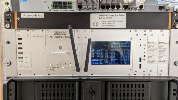
Right up front, we’ll stipulate that there’s absolutely no practical reason to do something like this. And hacker [Jon Petter Skagmo] admits that this is very much a “because I can” project. The idea is to support a bunch of old landline phones distributed around the house, and beyond, in a sort of glorified intercom system. The private exchange is entirely scratch-built, with a PIC32 acting as the heart of the system, performing such tasks as DTMF decoding, generating ring voltage, and even providing a CAN bus interface to his home automation system.

The main board supports five line interface daughterboards, which connect each phone to the switch via an RJ11 jack. The interface does the work of detecting when a phone goes off-hook, and does the actual connection between any two phones. A separate, special interface card provides an auto-patch capability using an RDA1846S RF transceiver module; with it, [Jon Petter] can connect to any phone in the system from a UHF handy-talkie. Check out the video below for more on that — it’s pretty neat!

We just love everything about this overengineered project — it’s clearly a labor of love, and the fit and finish really reflect that. And even though it’s not strictly old school, POTS projects like this always put us in the mood to watch the “Speedy Cutover” video one more time.

Continue reading “Homebrew Telephone Exchange Keeps The Family In Touch, In The House And Beyond”

Too Many Pixels

Sometimes simpler is more impressive than complicated, and part of this is certainly due to Arthur C. Clarke’s third law: “Any sufficiently advanced technology is indistinguishable from magic.”. It’s counter-intuitive, though, that a high-tech project would seem any less amazing than a simpler one, but hear me out.

I first noticed this ages ago, when we were ripping out the blue laser diodes from Casio XJ-A130 laser projectors back when this was the only way to get a powerful blue laser diode. Casio had bought up the world’s supply of the 1.5 W Nichias, and was putting 24 of them in each projector, making them worth more dead than alive, if you know what I mean. Anyway, we were putting on a laser show, and the bright blue diode laser was just what we needed.

RGB Laser show
A sweeter setup than mine, but you get the idea. 

Color laser setups take three or more different lasers, combine the beams, and then bounce them off of mirrors attached to galvos. Steer the mirrors around, and you can project vector images. It’s pretty cool tech, and involves some serious fine-tuning, but the irony here is that we were tearing apart a device with 788,736 microscopic DLP mirrors to point the lasers through just two. And yet, a DIY laser show is significantly cooler than just putting up your powerpoint on the office wall.

The same thing goes for 2D plotting machines like the AxiDraw. The astonishing tech behind any old laser printer is mind-numbing. Possibly literally. Why else would we think that art drawn out by a pen in the hands of a stepper-powered robot is cooler than the output of a 1600 DPI unit coming from HP’s stable? I mean, instead of running an hours-long job to put ink on paper with a pen, my Laserjet puts out an image in ten seconds. But it’s just not as much fun.

So here we are, in an age where there’s so darn much magic all around us, in the form of sufficiently advanced technology, that comprehensible devices are actually more impressive. And my guess is that it’s partly because it’s not surprising when a device that’s already magic does something magical. I mean, that’s just what it’s supposed to do. Duh!

But when something beautiful emerges from a pair of mirrors epoxied to shafts on springs turned by copper coils, that’s real magic.

DIY Magnet Handling Tool Puts An End To Placement Errors

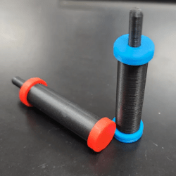
I’m sure we can all agree that the worst time to find out a magnet is the wrong way around is after glue has been applied. With that in mind, [erick.siders] created the parametric Magnet Placer tool.

Color-coded tools, one for each polarity.

Picking up and placing magnets into assemblies can be an error-prone process, because magnet polarity cannot be directly identified or sensed by either sight or fingertips. This tool helps by acting a lot like a suction pickup tool — press the plunger down, and a magnet can be picked up, release the plunger, and the magnet lets go. Simple, and effective.

Since the tool is polarity-dependent (depending on which orientation the pickup magnet is mounted into the internal plunger), [erick.siders] suggests printing two tools and color-coding them. That way, one can choose the right tool based on the situation and be confident that the magnets are right-side-up, every time.

The tools use a long metric bolt, a magnet, and a spring, but none of those parts are particularly critical. We also love the way that the end result has no gaps or openings into the moving parts, which means nothing can get caught on or inside anything during use or storage.

It’s a parametric design and the CAD files (in both Fusion 360 and STEP flavors) are provided, so modification should be a breeze. And if you happen to be using PrusaSlicer, remember you can now drop STEP format files directly in for slicing.