PCB Milling Tutorial

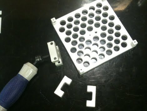
[Juan Jose Chong] put together a set of videos and a PDF guide to milling printed circuit boards. You’ll find the pair of videos, totaling about twenty-two minutes, embedded after the break. In them, [Jaun] details the techniques used by the IEEE chapter at Texas Tech University to mill PCBs instead of using the traditional method of etching them. We’ve long been a fan of milled PCBs and often dream about the day we can retire the old iron we use for the toner transfer method.

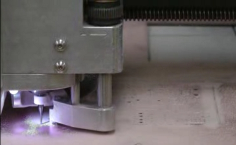
In the tutorial, IsoPro is the software used to control the mill. The CAM files from a PCB design program are imported – they can come from many different programs including EagleCAD. A few setup steps let the operator configure the resolution necessary to mill the correct tolerance and from there the paths that outline each trace are calculated in software. In order to facilitate double-sided boards a reference hole is drilled in the copper clad board to accept a post on the mill table. Tape down the substrate with some foil tape, set the depth of the end mill bit, and let the machine do its thing. [Juan’s] video illustrates how quickly this can produce a rather complicated board, finishing in around 20 minutes.

Continue reading “PCB Milling Tutorial”

CNC Mill Built From Junk And Hardware Store Parts

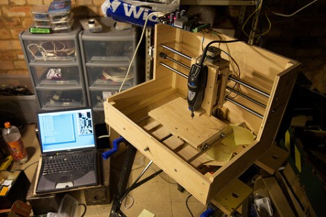
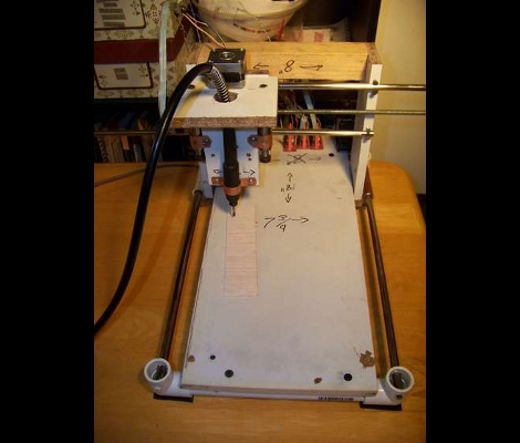
[Csshop] is setting a new bar for building an inexpensive CNC mill. Not only did he complete his build at a very low cost, but it seems to work quite well too. Check out the video after the break to see the device cut out thin wood parts for a toy plane.

The majority of the build uses scrap wood for the body of the mill. The business end of the device is a flexible rotary attachment for a Dremel tool which takes a lot of the weight and bulk out of the gantry assembly. Old flat bed scanners were gutted for the precision ground rod and bearings, as well as the three stepper motors used to drive the axes. An Arduino board controls the device, commanding the stepper motors via EasyDriver boards.

Once the hardware is assembled there’s still a fair amount of work to do. [Csshop] builds his designs in Google Sketchup, but some conversion is necessary to arrive at code that the Arduino will understand. He’s got a second project write-up that covers the software side of things.

Continue reading “CNC Mill Built From Junk And Hardware Store Parts”

Open Source 5-axis CNC Router

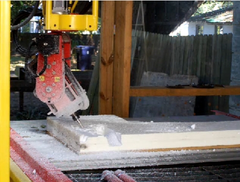
This 5-axis CNC router could soon be an open source tool. [Mike Calvino] built it for the School of Architecture at the University of Arkansas. It can be used as a router or as a plasma cutter/welder. Now he’s trying to raise some money that will underwrite his time and effort to develop and release instructions, design files, and specifications to make it an open source hardware project.

It is extremely large, and in addition to the X, Y, and Z axes that you’d expect to find on CNC machinery, it can tilt and rotate the cutting tool. This is not something you’re likely to build at home. But the availability of plans would be a huge contribution toward making machine tools accessible at a relatively small price tag. It’s not hard to image universities building this as a class project. We also think it would be a perfect group project for you and your buddies over at the local Hackerspace to undertake. Check out some milling action in the clip after the break.

Continue reading “Open Source 5-axis CNC Router”

Cobbling Together A CNC Mill

[Howard Matthews] never throws anything away, and because of it he was able to build this CNC mill using parts that he already had on hand. He pulled stepper motors out of broken stage light, precision rod and bearings from old dot matrix printers, and other various bits from his junk bin. We’ve seen [Howie’s] handi-work before, and this project is just as fun as his Land Rover’s replacement speedometer. Some highlights include manufacturing the nuts for the precision rod, and building a rail system for the bed of the machine. The latter looks a bit suspect, as any milling debris on the rails will cause you Z-axis problems, but now that he has bootstrapped a working mill perhaps he’ll machine an upgrade.

Update: Fixed the link, added video after the break.

Continue reading “Cobbling Together A CNC Mill”

CNC Machine From PC Parts

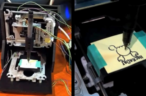
[Mike Rankin] built a small CNC machine using some PC parts. He repurposed two optical drives and a floppy drive to create the plotter seen drawing the Hackaday logo above. The X and Y axes use the stepper motor controlled read heads from two optical drives. The Z axis is built using the read head hardware from a floppy drive. A 3-axis controller module from eBay drives the little machine, keeping the cost quite low at around $45.

As you can see in the video after the break it does a great job as a plotter. [Mike] doesn’t think there’s enough power in the hardware to be used as a mill. We’d still like to try adding a flexible shaft rotary tool and see if this could mill some rudimentary PCBs, but maybe you need to shell out just a little bit more for that functionality. It might also be possible to use an etchant resist marker instead of toner transfer or photo-resist.

Continue reading “CNC Machine From PC Parts”

Project Enclosures The Right Way

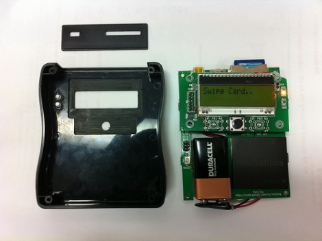
[Stephen Eaton] created an enclosure and shared his process in a pair of blog post. We thought is was amusing that he remarks on how rarely his projects get the to point that you’d want to make an enclosure for them. We’ve certainly got a lot of bare-PCB creations lying around. But when it does come time, we think his fabrication method is a good way to go.

First of all, he didn’t start from scratch. He already had a SparkFun project case sitting around. The problem is figuring how to make it work for your situation. We’ve used a drill, a Dremel, and a file in the past and that yields passable results but nothing that would be mistaken for anything other than a carefully mangled project box. [Stephen] decided to mill the openings he needed from the box, which yielded professional looking results. He started by emailing SparkFun and asking if they could give him a 3D model of the project box and the obliged. He then modeled the LCD screen, LED light pipes, button, USB port, and SD socket. From there it was off to the mill with a custom jig and a few tricks we think you’ll appreciate. The end result is just another reason to build the CNC mill you’ve had on your mind for so long.

Machined Steadicam, Steadier Than The Rest

No, the picture above is not a store made steadicam. Rather, a CNC machined one by [Matt]. Interestingly, unlike most steadicams we’ve seen before the gimbal is not the main focus of the design though an aluminum machined gimbal would make us drool. The central idea is allowing for X and Y axis adjustment to get oddly weighted bulky camera’s exact center of gravity. [Matt’s] steadicam is also designed to handle more weight than commercial versions, and (if you already have a CNC) to be much cheaper. There’s no video, but from the skill of craftsmanship we can safely assume it’s as good and level as some of the best.