Addressable 7-Segment Displays May Make Multiplexing A Thing Of The Past

[Sean Hodgins] has a knack for coming up with simple solutions that can make a big difference, but this is one of those “Why didn’t I think of that?” things: addressable seven-segment LED displays.

[Sean]’s design is basically a merging of everyone’s favorite Neopixel RGB LED driver with the ubiquitous seven-segment display. The WS2811 addressable RGB driver chip doesn’t necessarily have to drive three different color LEDs – it can drive three segments of the same display. With three of the chips on a single board, all seven segments plus the decimal point of a display can be controlled over a single data line. No more shift registers, no more multiplexing. And as a nice touch, individual displays can be ganged together with connectors on the back of each module. [Sean] has some code to support the display but is looking for someone to build a standalone library for it, so you might want to pitch in. Yes, he plans to sell the boards in his shop, but as with all his projects, this one is open source and everything you need to build your own is up on GitHub. The brief video below shows a few daisy-chained displays in action.

Like many of [Sean]’s designs, including this Arduino rapid design board, this is a simple way to get a tedious job done, and it wrings a lot of functionality from a single IO pin.

Continue reading “Addressable 7-Segment Displays May Make Multiplexing A Thing Of The Past”

New Method For Measuring Lots Of Resistors Using Very Few Wires

[Daqq] is back at it again with the linear algebra, and he’s now come up with a method for determining the resistance of lots of resistors using little of wires and loads of math.

Like any reasonable person, [daqq] decided it would be fun to “solve one of those nasty [electrical engineering] puzzles/exercises where you start out with a horrible mess of wires and resistors and you are supposed to calculate the resistance between two nodes.” You know, just an average Saturday night. At the time, he was also fascinated by Charlieplexing – an awesome technique that either allows one to control multiple polarized components, such as LEDs, simply by connecting them in a specific way. After toying with the idea for a while, [daqq] found that using just Charlieplexing would be“a horrible mess” but he didn’t stop there. Drawing inspiration from Charlieplexing, he came up with the idea to connect things in such a way that every node is connected by one connection to every other node – a complete graph from a topological view point (this makes so much more sense visually). From here, he was able to set pins to HIGH, LOW, or INPUT and gather all the data needed to solve his linear system of equations.

Now, there is a balance to everything, and while this system can determine the resistance of .5*N(N-1) resistors using just N wires, it also a memory and computation hungry method. Oh well, can’t have it all. But, while it’s computationally hungry, [daqq] got it working on an ATMega32, so it’s not an unmanageable feat. And, let’s not forget to mention [daqq’s] wonderful writing. Even if you don’t know linear algebra (or would rather forget), it’s a good read from a theory perspective. So good, in fact, that [daqq] is getting published in Circuit Cellar!

We love to see theory in the hacker world, so keep it coming! But, while we wait (wink wink), there’s always time to review the basic Hacker Calculus and check out our past math-related articles.

Octosonar Is 8X Better Than Monosonar

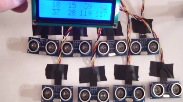
The HC-SR04 sonar modules are available for a mere pittance and, with some coaxing, can do a pretty decent job of helping your robot measure the distance to the nearest wall. But when sellers on eBay are shipping these things in ten-packs, why would you stop at mounting just one or two on your ‘bot? Octosonar is a hardware and Arduino software library that’ll get you up and running with up to eight sonar sensors in short order.

Octosonar uses an I2C multiplexer to send the “start” trigger pulses, and an eight-way OR gate to return the “echo” signal back to the host microcontroller. The software library then sends the I2C command to select and trigger a sonar module, and a couple of interrupt routines watch the “echo” line to figure out the time of flight, and thus the distance.

Having two sonars on each side of a rectangular robot allows it move parallel to a wall in a straightforward fashion: steer toward or away from the wall until they match. Watch the video below for a demo of this very simple setup. (But also note where the robot’s 45-degree blind spot is: bump-bump-bump!)

Continue reading “Octosonar Is 8X Better Than Monosonar”

Multiplexing Pi Cameras

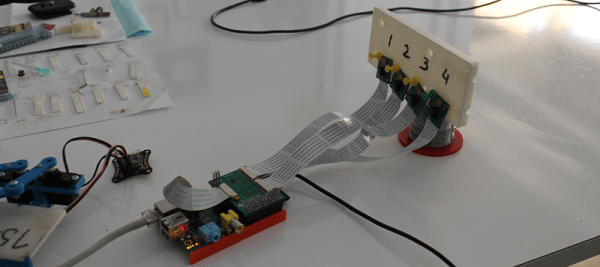
The Raspberry Pi and its cool camera add-on is a great way to send images and video up to the Intertubes, but what if you want to monitor more than one scene? The IVPort can multiplex up to sixteen of these Raspi camera modules, giving the Pi sixteen different views on the world and a ridiculously high stack of boards connected to the GPIO header.

The Raspberry Pi’s CSI interface uses high-speed data lines from the camera to the CPU to get a lot of image data quickly. Controlling the camera, on the other hand, uses regular old GPIOs, the same kind that are broken out on the header. We’ve seen builds that reuse these GPIOs to blink a LED, but with a breakout board with additional camera connectors, it’s possible to use normal GPIO lines in place of the camera port GPIOs.

The result is a stackable extension board that splits the camera port in twain, allowing four Raspi cameras to be connected. Stack another board on top and you can add four more cameras. A total of four of these boards can be stacked together, multiplexing sixteen Raspberry Pi cameras.

As far as the obvious, ‘why’ question goes, there are a few interesting things you can do with a dozen or so computer controlled cameras. The obvious choice would be a bullet time camera rig, something this board should be capable of, given its time to switch between channels is only 50ns. Videos below.

Continue reading “Multiplexing Pi Cameras”

Color Multiplexing Through Fiber Optics

If you want to go high bandwidth, fiber optics is the way to go. From trans-oceanic cables to the yet-unseen ‘fiber to every home,’ fiber optics allows a lot more bandwidth than a copper cable. In low-bandwidth applications, fiber optic cable transmits data using one color of light. There’s a way to get more bandwidth out of a fiber optic cable, as [Shahriar] found out while experimenting with an RGB LED.

For his experiment, [Shahriar] used a BlinkM programmable RGB LED and a Sparkfun color sensor. In fiber optic lines with one light, it is possible to send many simultaneously using PWM, but noise becomes a problem at high data rates. Using an RGB LED, [Shahriar] sends three levels of Red, Green, and Blue to transmit 9 bits at a time – perfect for sending a byte with a parity check in one quick light burst.

[Shahriar]’s technique is exactly how the pros pump massive amounts of data through a single fiber optic cable. All the tools, code, and MATLAB functions are available on [Shahriar]’s site, ready to be used by anyone wanting to experiment for themselves.

In the video after the break, [Shahriar] breaks everything down, including the tools, theory, and actual circuits. It’s an amazing video demo, so thorough we’re wondering if [Shahriar] has any teaching ambitions.

Continue reading “Color Multiplexing Through Fiber Optics”

Upgrading RAM In An Arduino Mega

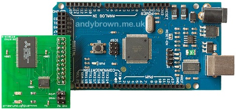
[Andy] stuffed some more RAM onto an Arduino Mega and his three-part walk through on the design, construction, and software is a great read and one of the more ‘hard core’ Arduino builds we’ve seen.

The build is centered around a 512K × 8 SRAM module [PDF warning]. Because the RAM is divided up into about 512,000 chunks of 8 bits, the Arduino has to access the RAM through 16 ‘address lines’, then send the data through 8 ‘data lines’. [Andy] didn’t want to use up 24 pins on his Arduino, so he used a latch to multiplex the lowest 8 address lines and the data lines together. With the 512KB RAM expansion installed, the Mega is able to address a whopping 520 Kilobytes.

We’ve seen a few builds that have been limited by the amount of RAM available in the Arduino, like capturing video and some robot hacks, and adding some more RAM to those builds would be great. Multiplexing data and address lines using a latch can be expanded even further, but 520KB ought to be enough for anybody.

A Beginner’s Guide To LED Matrices

led_tutorial

[Rajendra Bhatt] wrote in to share a tutorial he put together demonstrating the basics of using LED dot matrix displays. While this subject might be old hat to many out there, his helpful walkthroughs are geared more towards beginners who are exploring various electronics concepts for the first time.

He explains the theory behind LED displays using a PIC-driven 5×7 matrix as an example. He discusses persistence of vision and how tricking the human eye can save you quite a bit of time and a whole lot of pins. Multiplexing is broken down into its most basic steps, which [Rajendra] illustrates by showing how a letter would be drawn on the LED display one column at a time. The use of a ULN2803A Darlington Array is also discussed, and he details why it is used when pulling the five columns of LEDs to ground.

The only portion of the tutorial we thought could be expanded upon was the programming section. While he does show how each letter of the alphabet can be displayed via a series of five hex values, he does not cover the “why” part of the process. Obviously while anyone familiar with binary and hex can figure it out in pretty short order, we think that it would be a great place to pause and expand the readers’ knowledge even more.

Overall it’s a useful tutorial, and most beginners would likely find it quite helpful.