Testing The Limits Of Home PCB Etching

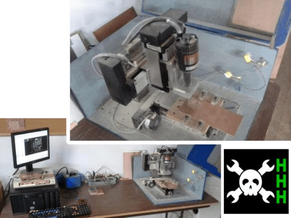
[Quinn Dunki]’s Veronica, a homebrew computer based on the 6502 CPU, is coming along quite nicely. She’s just finished the input board that gives Veronica inputs for a keyboard and two old Nintendo gamepads. [Quinn] is building this computer all by her lonesome, including etching all the PCBs. She’s gotten very, very good at etching her own boards, but this input board did inspire a few facepalming moments.

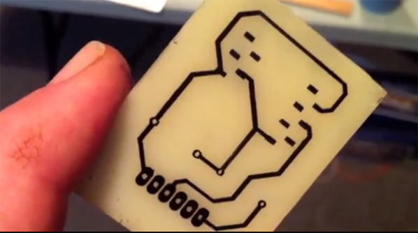
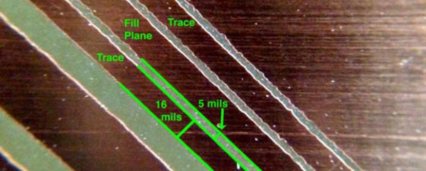
In an earlier post, [Quinn] went over her PCB etching capabilities. As demonstrated by the pic above, she’s able to print 16 mil traces with 5 mil separation. This is just about as good as you can get with homebrew PCBs, but it’s not without its problems.

[Quinn] is using a photographic process for her boards where two copies of a mask is printed on an acetate sheet, doubled up, and laid down on a pre-sensitized copper board. The requirement for two layers of toner was found by experience – with only one layer of toner blocking UV light, [Quinn] got some terrible pitting on her traces and ground planes.

Two photographic masks means the masks must be precisely aligned. This example shows what happens when the acetate sheets are ever so slightly misaligned. With a 5 mil gap between traces, [Quinn] needs to align the masks to within ±2.5 mils; difficult to do by eye, and very hard once you factor in flexing and clamping them down to the copper board.

Even when this process goes perfectly, [Quinn] is pushing the limits of a laser printer. When printing at 600 dpi, the pixels of the print are about 1.5 mils. While GIMP, printer drivers, and the printer itself have some fancy software to help with the interpolation, [Quinn] is still seeing ‘bumps’ on the edges of perfectly aligned parts. This is one of those things that really makes you step back and realize how amazing fabbing PCBs at home actually is.

With most of the hardware for Veronica out of the way, it’s just about time for [Quinn] to start programming her baby. We’re not expecting a full-blown operating system and compiler, but those NES gamepads are probably crying out for some use.

A Touch Scroll Wheel Via OpenSCAD

touch

Recent experiments with the Arduino CapSense library led [Bryan] around the Internet looking for interesting applications. He hit upon a very cool touch scroll wheel made entirely with PCB traces, but the geometry – three interleaved zig zags is impossible to build in the decidedly ungeometric Eagle PCB package. One thing leads to another and now [Bryan] has a cap touch wheel Eagle part designed entirely in OpenSCAD.

The touch scroll wheel implementation [Bryan] found came from an ST touch controller datasheet and used oddly-shaped patterns to create a capacities sensor. Eagle is terrible for designing anything that isn’t laid out at a 45 degree angle, so he fired up OpenSCAD to draw these triangles. Importing into Eagle was another challenge, but a quick Ruby script to convert a DXF file into a set of coordinates for Eagle’s POLYGON command made everything very easy.

If OpenSCADing touch sensors isn’t your thing, there’s also an Eagle library full of them – something we found last week.

Printing Printed Circuit Boards

circuit

We really respect the old timers out there and their amazing ways of crafting PCBs; they used black tape on clear acetate sheets to create single layers of PCBs with a photoetching process. Now creating a PCB is a simple matter of opening up a CAD package, but like the old timers we’re still dealing with nasty chemicals or long shipping times from China.

The EX¹, a new robot on Kickstarter – hopes to change that. They’ve created a PCB fabrication process that’s as simple as printing something with an inkjet printer. Just put in a piece of substrate – anything from Kapton to acrylic to fabric – and in a few minutes you have a single-sided PCB in your hands.

The printer dispenses two chemicals, silver nitrate and ascorbic acid, that react and produce traces and pads for the circuit. Right now, the EX¹ is limited to single-side boards, but experiments on creating multi layer boards are ongoing.

In any event, we’re really impressed with how simple the EX¹ setup actually is. Inkjet is a mature, well understood technology with more than enough resolution for simple homebrew circuits, and the AgNO3 + Vitamin C formula could easily be adapted to an inkjet printer modification.

Hackaday Links: November 10, 2013

hackaday-links-chain

[Henryk Gasperowicz], the wizard of electrons who makes LEDs glow for no apparent reason, has put up another one of his troll physics circuits. We have no idea how he does it (he does say he’s using wireless energy transmission) so a few solution videos would be cool, [Henryk].

Altoids tins make great electronic enclosures, but how about designing your PCBs to fit mint and gum containers? Here’s a Trident USBASP, a tiny Tic Tac ISP thingy, and a Mentos USB to JTAG interface.

By the end of this week, the PS4 will be out, along with the new PS4 camera. It’s a great camera – 1280×800 at 60Hz – but unless someone develops a driver for it, it shall forever remain tethered to a PS4. Luckily, there’s a project to develop a PS4 camera driver, so if you have some USB 3.0 experience, give it a shot.

Multimeter teardowns? [David]’s got multimeter teardowns. It’s an HP 3455A, a huge bench top unit from the 80s. This is, or was, pro equipment and strange esoteric components definitely make a showing. ±0.01% resistors? Yep. Part two has some pics of the guts and a whole ton of logic.

The US Air Force Academy just moved their embedded systems course over to the MSP430. Course director [Capt Todd Branchflower] just put all the course materials online, with the notes, datasheets, and labs available on Github.

Make Any Shape Board In Eagle

circuit2

[Bryan] has been working on a very nice analog LED clock circuit, but when it came time to lay out the parts in Eagle, he was somewhat miffed by the inability to create designs in his Eagle boards. Eagle is a fine tool for laying out circuits, but when it comes to making strangely shaped PCBs, Eagle just isn’t the right tool.

The solution to this problem was to create the board outline in OpenSCAD. The desired shape of [Bryan]’s clock was easily designed, but importing the shape into an Eagle layer was another matter entirely.

OpenSCAD, though, can output 2D shapes to the DXF format. Getting the DXF board into Eagle required [Bryan] to write a script that outputs Eagle WIRE commands. Pasting these commands into the command line gave [Bryan] a perfectly shaped PCB.

Since DXF is supported by every drawing package on the planet, [Bryan]’s 20 line script could also be used for much more intricate designs. If you have an incredibly complex Illustrator drawing that deserves to be a PCB, it doesn’t get much easier than tossing it through a script.

Perfect PCBs With An Inkjet Printer

Instead of mucking about fabbing PCBs with the toner transfer method, or making masks for photosensitive boards, the holy grail of at-home circuit board manufacturing is a direct inkjet-to-etch method. [Don] isn’t quite there yet, but his method of producing circuit boards at home is one of the easiest we’ve ever seen.

[Don]’s boards begin by taking the output from Eagle and printing them with an Epson Artisan 50 inkjet printer. By sticking a piece of cardstock in the printer before the copper board, he’s able to precisely align the traces and pads onto the copper board.

When the board comes out of the printer, it’s only covered in ink. While some specialty inks are enough of an etch resist, [Don] comes up with a clever way to make sure acid doesn’t eat away copper in the needed places – he simply dusts on toner from a copier or laser printer, blows off the excess, and bakes the entire board in a toaster oven.

The result, seen above, are perfect traces on a circuit board without the need for ironing sheets of photo paper onto copper boards.

As far as the, “why didn’t someone think of this sooner” ideas go, this one is at the top. [Don] says the method should work  on sheets of aluminum for printing solder paste masks. Impressive work, and now the only thing left to do is getting two-layer boards down pat. For more direct to copper printing check out the hacks we’ve covered in years past.

Continue reading “Perfect PCBs With An Inkjet Printer”

HHH: PCB Mill From Connecticut Hackerspace

hhh-pcb-mill-CT-hackerspace

The latest Hackaday Hackerspace Henchmen entry comes from [Bremster] and the Connecticut Hackerspace. He mentions that he’s been meaning to write about the PCB/engraving mill used at the hackerspace for some time, but it was the HHH program which motivated him to do so. Yay! That’s exactly what we envisioned with this and we hope there are more submissions which will encourage us to continue and expand the program.

We think this is a perfect CNC project for any hackerspace whose members are into electronics. It’s compact, and we find milling PCBs to be more desirable than chemically etching them; the tool should get quite a bit of use. This particular build uses x, y, and z axis hardware which was pulled separately from unknown machinery. Like any good hacking project, the fabrication process was so addictive that [Bremster] stayed at the space all night, breaking at 5am to shower and eat before heading to work.

It originally used a Dremel rotary tool but had too much play in the mounting mechanism. When they replaced it with the motor shown above they also machined an aluminum bracket that dramatically stabilizes the cutting bit. This results in clean PCBs, and they’ve even used it to make stamps for their hackerspace passports. There is an enclosure attached, which has been hinged to the right for the two images above.

Check out the demo video below, and get your own CNC submission in for the HHH program before the October 31st deadline.

Continue reading “HHH: PCB Mill From Connecticut Hackerspace”