One-man SMD Assembly Line Shares A Lot Of Tips About Doing It Right

Need to use that antiquated hardware that can only be connected via a parallel port? It might take you some time to find a computer that still has one of those, or you could try out this USB to Parallel port converter. It’s not limited to working with printers, as the driver builds a virtual parallel port that you should be able to use for any purpose. But what we’re really interested in here isn’t the converter itself, but the build process. [Henrik Haftmann] posted a three-part series of videos on the assembly process, which you can watch after the break.

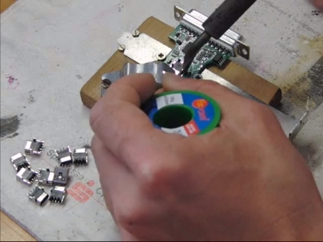
The build is mostly surface mount soldering with just a handful of components that need to be hand soldered. The first of his videos shows him stenciling solder paste onto the boards. From what we can see it looks like he built a nice jig for this using scrap pieces of copper-clad which match the thickness of the PCB, and hold it and the stencil securely in place. There’s a bunch of other tips you can glean from the videos, like the image seen above. It’s a clamp that holds the PCB and USB jack together while they are soldered.

If you’re ever thinking of assembling a bunch of boards you should set aside thirty minutes to watch them all.

Continue reading “One-man SMD Assembly Line Shares A Lot Of Tips About Doing It Right”

A Stackable Motor Driver Shield For The Arduino

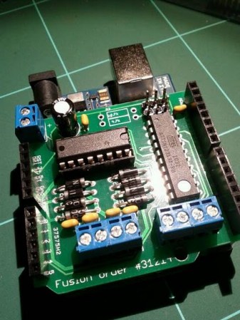
The Arduino has been used for many purposes, and  “shields” are available to make many common tasks easier.  However, [Nick] wanted a stackable motor driver shield, so he build one himself!. There are many motor driver shields available for the Arduino, however, there aren’t any that allow one to drive as many motors as were needed for his project, and none that were stackable.

[Nick] had no experience designing and fabricating a custom board, but decided to try his hand at it anyway. Armed with a free version of [Eagle] PCB design software, he designed the board that he needed then sent it to [Seeed] to be manufactured. According to his article, a quantity of 10 Arduino-sized boards can be purchased for the price of $25. At that price point, some hobbyists may want to consider this option rather than manually creating their own circuit.

According to [Nick], he was able to manufacture his first board with no errors on his first run! Not bad for his first try at something like this.

DIY PCB Exposure Box Looks Professionally Made

diy_double_sided_exposure_box

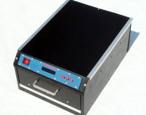
[Stynus] was frustrated with the fact that he would have to flip his PCBs over mid way through the exposure process, so he decided the best course of action would be to build his own double-sided PCB exposure box.

He scored some UV LEDs on eBay, and after waiting a few weeks for PCBs to arrive, he was ready to start construction. The box contains a sliding glass shelf, which is positioned between two sets of LED panels. The setup lets him simultaneously etch both sides of any PCB, up to 20cm x 30cm in size. The exposure box is run by a PIC 16F628P and features an LCD status panel as well as a small handful of controls. [Stynus] programmed the box to retain the length of the last exposure, making it easy to replicate his results time after time.

Towards the end of the build log he shows off some pictures of the completed exposure box, which looks very professionally done. It’s a great job all around, and we would gladly take one for our workshop in a heartbeat.

Juice Bridge Powers Your Breadboard In A Snap

juice_bridge_breadboard_power_bridge

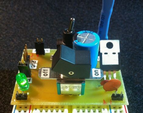
[Quinn Dunki] got tired of messing around with wires when connecting things to her benchtop power supply, so she built herself useful little power bridge that plugs directly into any standard breadboard.

The board is small and simple, but quite useful all the same. It was built to power both sides of the breadboard, and it can be easily switched between an unregulated power supply and a regulated 5v supply. An ammeter can be attached to the board via a pair of pins she set aside, allowing her to easily measure the current draw of the entire circuit.

We think her “Juice Bridge” would be very useful to anyone who frequently prototypes on breadboards. In fact, it would be a fantastic beginner project since it involves etching and developing PCBs as well as some simple soldering, while resulting in a handy takeaway tool at the same time.

If you want to build one of your own, [Quinn] has the schematics and Eagle PCB files available for download on her site.

Visualizing PCB Revisions Using A Gerber Viewer

gerber_schematic_highlighting

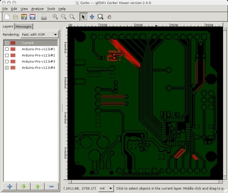
We all know that Eagle has its share of shortcomings. Instructables user [westfw] was particularly annoyed by the fact that while Eagle keeps copies of up to 10 revisions of your board, it cannot open those files without resorting to manually renaming each one. Even more frustrating to him is the fact that you can’t use Eagle to view two files simultaneously in order to compare layouts. This made hunting down changes quite tedious, so he started looking for a better way to do things.

While using his favorite open-source gerber viewer gerbv, he noticed that the application let him load multiple copies of the same layer, XORing the PCBs’ colors together. Realizing that with some clever color selection, he could use gerbv to automatically highlight layout differences, he set off to automate the process.

The resulting script works on any flavor of *nix, and should play nice in Windows under cygwin as well. The script reads through Eagle backup files, renaming them and tweaking the colors so that when XORed, they show up as bright red areas in gerbv. It’s a simple yet handy tool to have on hand if you happen to do a lot of PCB design.

Cheap And Easy PCB Agitator From An Old CD-ROM

cdrom_pcb_agitator

Instructables user [mzsolt] enjoyed making his own PCBs, but he wanted to speed up the etching process just a bit. While some people put together elaborate bubble tanks and agitators, he wanted to keep his simple and more importantly, cheap.

He looked around the house and discovered an ancient CD-ROM drive that was collecting dust, which he figured would make a great agitator for smaller projects. He picked up a decade counter and a handful of other cheap components, then got busy pulling the drive apart. He connected the motor and the drive’s limit switches to the decade counter, which controls the entire setup.

When powered on, the drive ejects, taking his container full of etchant with it. When the drive hits the outer limit switch, the decade counter reverses the motor until it hits the inner switch, reversing the motor once again.

As you can see in the video below, it works reasonably well. He suggests using a variable power supply to regulate the motor’s speed, but a variable pot would probably work just as well. Obviously the agitator is best suited for smaller projects, but since it was so cheap to put together, you won’t hear us complaining.

Continue reading “Cheap And Easy PCB Agitator From An Old CD-ROM”

Importing PCB Layout Into Google Sketchup

If you’ve been spending hours with the digital calipers while designing enclosures for your circuit boards there may be a better way. [Phil] tipped us off about a new software package that will let you import PCB layout files into Google Sketchup. This way you can start working on the enclosure in CAD before you’ve populated your first board. Of course this adds to the pain of realizing there’s an error in your layout, but what are you going to do?

The free software was developed by RS Components, a European component distributor. It takes IDF files, which can be exported from most PCB design software, and converts them to a format compatible with Sketchup, Google’s 3D design software. For those who enjoy a very dry demonstration video you won’t want to skip seeing what we’ve embedded after the jump.

We’re kind of surprised that this hasn’t already been done. If it has, leave a link in the comments.

Continue reading “Importing PCB Layout Into Google Sketchup”