BAMF2011: ChipKIT Is Arduino To The Power Of 32

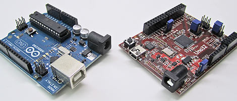
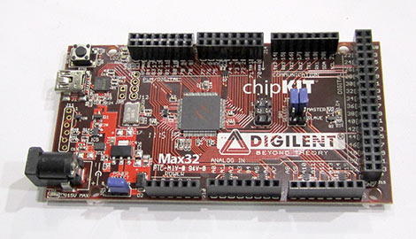
If you’ve been hungry for more power for your microcontroller projects, but reluctant to dump your investment in Arduino shields or the libraries and community knowledge that go with them all, Digilent has you covered. Their new chipKIT boards are built around the Microchip PIC32 MCU…a powerful 32-bit chip that until recently was left out of the cross-platform scene. A majority of code and quite a number of Arduino shields will work “out of the box” with the chipKIT, and the familiar development tools are available for all three major operating systems: Windows, Mac and Linux.

We first mentioned these a couple weeks ago, but the software was unavailable at the time. Seeing the development tools in action was quite unexpected…

Continue reading “BAMF2011: ChipKIT Is Arduino To The Power Of 32”

A Computer-controlled Shutter For Polaroid Packfilm Cameras

[Georg] wanted to modify his old Polaroid land camera so he could have control over the exposure time. The resulting project is a neat hack, if we say so ourselves.

The stock electronics in Polaroid 100-series Packfilm cameras were a simple analog computer that integrates current through a light-sensitive resistor. This is a simple, low tech way to make sure the exposure time is correct. The usual mod would be to replace photoresistor with a potentiometer, but [Georg] had little success with this modification. After tearing the old hack out of the camera, [Georg] replaced the ancient electronics with a a PIC microcontroller, and is now able to control the shutter in increments down to 1/512th of a second.

Shutter timing is read by a PIC12F629 μC with a BCD encoder. [Georg] kept the shutter magnet setup, and also added a ‘BULB’ routine that holds the shutter open as long as the button is held down. The test photos are quite nice, even if from a 1960s Polaroid Land Camera. Check out the video of [Georg] running though the shutter settings after the break.

Continue reading “A Computer-controlled Shutter For Polaroid Packfilm Cameras”

An Alarm For Every Day Of The Week

If you don’t have a 9-to-5 type of job you might find yourself constantly resetting your alarm clock as your calendar commitments change. [Lucas] finally got fed up with the nightly ritual and decided to build his own alarm clock which has unique settings for each day of the week (translated).

The display itself is an LM044L 20×4 character display. This provides a viewing area that is about 3″x1″ and since it’s an HD44780 compliant LCD screen, writing data to it takes very little effort (and RAM) compared to a graphic LCD. A PIC 18F2550 drives the device, taking input from a half-dozen buttons, driving the display, and turning on the enclosed buzzer when it’s time to get up. There’s a backup battery which will keep the settings when power is lost. The daily alarms, current time, and back light brightness can all be adjusted from the four screens that make up the settings menus. The only thing that it’s missing is a precision timekeeper, but that should be easy to add either by measuring the frequency of the mains or by using an RTC chip.

Awesome Custom Disco Basement

led_shelves

[Evan] is one of those neighbors you only wish you had.

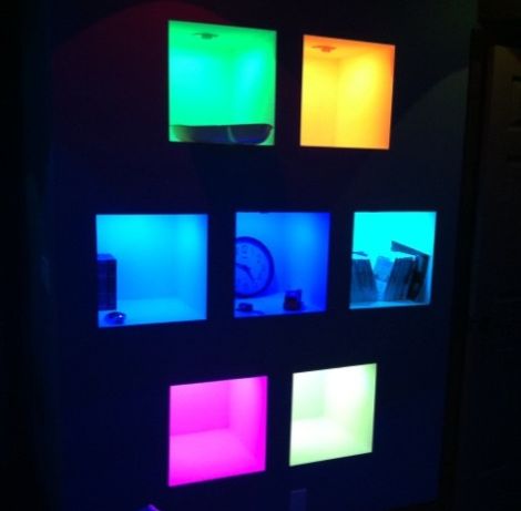
His neighbors were renovating their basement for use as home theater, and he stopped by to check out how things were coming along. While there, he suggested they add some LED lighting to their shelving unit to make them pop. His neighbors were game, so he sourced some cheap RGB LEDs online and began working on the circuits and firmware needed to control the lights. His neighbors wrote some custom software that interfaces with iTunes to create a neat visualization in the shelving unit whenever music is played.

Once everything was complete, his neighbors informed him that they wanted an additional 20 overhead can lights and a set of 4 wall sconces wired up as well. Needless to say he was pretty excited, so he got busy wiring up the remainder of the basement.

He pushed the installation’s PIC microcontroller about as far as he possibly could, resulting in the awesome show seen in the video below.

Needless to say, it’s pretty impressive, though we wish we could have a peek at the code used to run everything. Wink, wink, nudge, nudge.

Continue reading “Awesome Custom Disco Basement”

Adding MIDI To A Very Old Drum Machine

Long before drum machines played samples from an SD card or EPROM, drum sounds were analog – just filtered waveforms and noise. To the modern eye, these are very primitive machines, but for [Andrew], they’re the inspiration for this brilliant hack.

[Andrew] took a Roland CR-68 drum machine from 1978 and added MIDI input with the help of a PIC microcontroller. Not wanting to modify the look of the machine, [Andrew] programmed the PIC to watch the START/STOP button when the the unit is powered on. If the button is held down, the PIC enters it’s programming mode, where the sounds from the CR-68 can be mapped to an individual note on a MIDI controller. There’s no mention if the TRIGGER IN is queried by the PIC to modify the tempo of the preset patterns, but we assume that would be a relatively trivial implementation. Still, very impressive for a machine made 4 years before MIDI.

We love [Andrew]’s work, and we’re happy for any future owner that he documented how to use his device (and cleverly taped that to the bottom of the drum machine). It’s very nice to see old drum machines being used for more than doorstops after their samples have been recorded. Check out the video of [Andrew]’s walk through after the break.

Continue reading “Adding MIDI To A Very Old Drum Machine”

Improve Charlieplexing Performance With Interrupts

single_chip_led_matrix

[Dmitry] was shopping for LEDs and accidentally pulled the trigger on the wrong type. Since he didn’t want to be wasteful, he figured he should at least take the time to build something with them.

A LED matrix display was the obvious project choice, but he only had a PIC16F688 at his disposal. Since the micro controller only has 11 output pins, charlieplexing was the only way he would be able to light the entire matrix.

While testing his LED array, he found charlieplexing to be a bit disappointing. The fact that the LEDs can get relatively dim, depending on the number of units lit at any particular time struck him as annoying.

In order to improve the performance of his charlieplexed array, he first decided to scan through all of the LEDs rather than just those that needed to be lit. This ensured that all of his LEDs had the same 1/110 duty cycle and were always as bright as possible. He also chose to use interrupts when lighting the LEDs. This meant that his code does not need to take into consideration any specific timing requirements to maintain persistence of vision. He also double-buffers the display to help reduce flicker.

He says that he ran into certain constraints with the PIC chip he chose, so he used a handful of lookup tables to ensure smooth operation of his display. He was quite satisfied with the results, and we think that the interrupt-driven display looks like it works just fine from where we’re standing as well.

Be sure to stick around for a quick video explaining and demonstrating his single-chip LED matrix.

Continue reading “Improve Charlieplexing Performance With Interrupts”

A Beginner’s Guide To LED Matrices

led_tutorial

[Rajendra Bhatt] wrote in to share a tutorial he put together demonstrating the basics of using LED dot matrix displays. While this subject might be old hat to many out there, his helpful walkthroughs are geared more towards beginners who are exploring various electronics concepts for the first time.

He explains the theory behind LED displays using a PIC-driven 5×7 matrix as an example. He discusses persistence of vision and how tricking the human eye can save you quite a bit of time and a whole lot of pins. Multiplexing is broken down into its most basic steps, which [Rajendra] illustrates by showing how a letter would be drawn on the LED display one column at a time. The use of a ULN2803A Darlington Array is also discussed, and he details why it is used when pulling the five columns of LEDs to ground.

The only portion of the tutorial we thought could be expanded upon was the programming section. While he does show how each letter of the alphabet can be displayed via a series of five hex values, he does not cover the “why” part of the process. Obviously while anyone familiar with binary and hex can figure it out in pretty short order, we think that it would be a great place to pause and expand the readers’ knowledge even more.

Overall it’s a useful tutorial, and most beginners would likely find it quite helpful.