Wood burning can be quite a striking art form, but who wants to be stuck using an old-fashioned resistive heating element to char wood? You could go with laser engraving, of course, but that seems to take too much of the human touch out of it. So why not try a mini plasma pen and blow torch powered by a fancy cigarette lighter?
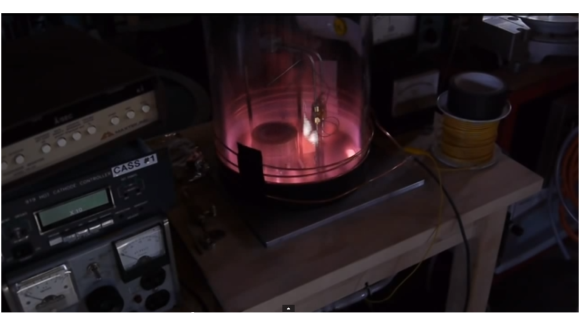
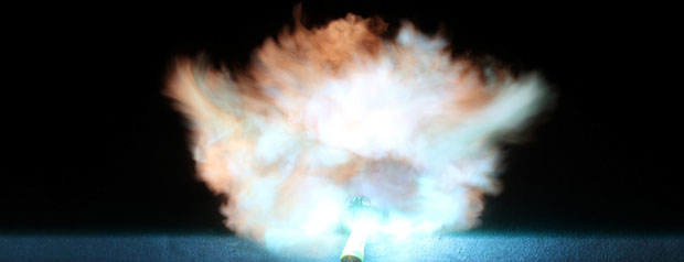
Arc lighters are rechargeable electronic lighters that look like a tiny stun-gun, and [NightHawkInLight] has been coming up with some interesting hacks for them. In this case, he extended the electrode leads out and mounted them to a wooden handle. The spark gap is only about 2mm, but the resulting arc is plenty hot enough to char wood with considerable precision. You’ve got to work fast, though, or the high voltage will start finding interesting paths through the char, producing Lichtenberg figures. And if a micro-scale blow torch is a tool you need, [NightHawkInLight] has got that covered too – a small brass tube with a pinched-off nozzle hooked to an aquarium pump provides the pressure for that.
Might there be other applications for this beyond pyrography? Maybe soldering or desoldering? Of non-ESD sensitive components, naturally.