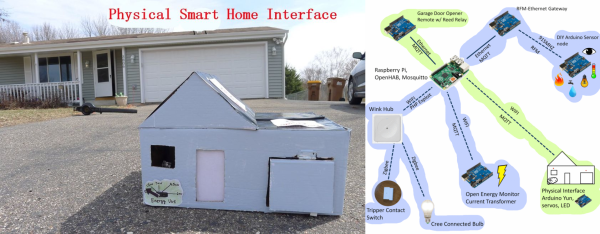
Everyone’s Favorite Energy Meter Hack, Now Wireless

[Kalle] is at it again with more hacks on electricity use meters. This time, the meter has been hacked to stream their data over the aether wirelessly. Now, data can be grabbed from multiple devices simultaneously, making the possibilities for home energy monitoring limitless

The first project [Kalle] did involved finding a meter from China with capabilities similar to (and cheaper than) the Kill-a-Watt meters. Unlike the Kill-a-Watt which spits out analog values, the Chinese meter sent digital information out on a ribbon cable with the bus lines labeled. Since the meter was so hackable, [Kalle] took it even further in this hack.

With those pesky wires out of the way, the device now uses an Arduino Pro Mini to sniff the energy meter’s data stream. Then it transmits the data wirelessly with a nRF34L01+ transceiver. As a perk, all of these chips fit inside the case of the energy meter, making this a very tidy hack indeed. The project code an incredible amount of detail is available on the project site, so be sure to check this one out for all of your energy monitoring needs!

Cheap Power Meter

Digital Data From A Cheap Power Meter

Power meters like the Kill-A-Watt are great for keeping track of energy usage, and are also very hackable. The Kill-a-Watt in particular puts out analog signals proportional to current and voltage, which makes it easy to interface with a microcontroller.

Although reading analog voltages is easy enough, [Kalle] found a cheap Chinese power meter that is even more hackable. These inexpensive power meters cost about the same as a first-generation Kill-a-Watt, but they directly stream out digital data. The power meter [Kalle] hacked has a non-US plug, but the meter is available from the usual suppliers (eBay, Aliexpress, etc) with a 3-prong US plug and 120v rating.

After breaking out a logic analyzer, [Kalle] discovered that the meter constantly streams voltage, current, and power data from the measurement board to the display board on a SPI-like bus. The ribbon cable inside the meter even has the clock and data bus lines clearly labelled. [Kalle] went on to reverse-engineer the protocol and write an Arduino sketch that parses the stream, making it even easier to integrate this meter into your next power monitoring project.

Electricity Monitoring With A Light-to-Voltage Sensor, MQTT And Some Duct Tape

Bh6mcz_CUAAuI3V

When it comes down to energy management, having real-time data is key. But rarely is up-to-the-minute kilowatt hour information given out freely by a Utility company, which makes it extremely hard to adjust spending habits during the billing cycle. So when we heard about [Jon]’s project to translate light signals radiating out of his meter, we had to check it out.

From the looks of it, his hardware configuration is relatively simple. All it uses is a TSL261 Light-to-Voltage sensor connected to an Arduino with an Ethernet shield attached. The sensor is then taped above the meter’s flashing LED, which flickers whenever a pulse is sent out indicating every time a watt of electricity is used. His configuration is specific to the type of meter that was installed by his Utility, and there is no guarantee that all the meters deployed by that company are the same. But it is a good start towards a better energy monitoring solution.

And the entire process is documented on [Jon]’s website, allowing for more energy-curious people to see what it took to get it all hooked up. In it, he describes how to get started with MQTT, which is a machine-to-machine (M2M)/”Internet of Things” connectivity protocol, to produce a real-time graph, streaming data in from a live feed.

Continue reading “Electricity Monitoring With A Light-to-Voltage Sensor, MQTT And Some Duct Tape”

A WiFi Home Power Meter

ac
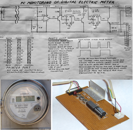
For his masters at Cornell, [Christopher McNally] designed a simple, non intrusive home power meter capable of doing everything a ‘smart meter’ can do – log power consumption throughout a home, and display a log of a home’s power consumption over WiFi. He’s even testing out some interesting ideas, like automatically detecting when specific devices turn on by reading the current data.

From [Chris]'[Jeramy] developed his system around the Arduino and a Ethernet shield, taking care of networking and choosing a micro, leaving him more time to develop the more interesting part of the project: sensing current. For this he used a small, clip-on current transducer. This sensor generates up to 10 VAC across a resistor, but the Arduino doesn’t play well with AC, requiring a small rectifier built around an op amp.

While the project works as a homebrew smart meter, [Jeramy] wasn’t able to automatically detect when certain devices were powered on. This is partly due to the fact that changes in current were only seen in magnitude and not waveform. Also, if two devices were powered on at the same time, the software would see that as a larger device that draws the sum of the current of two smaller devices. Still, [Jeramy] came up with a cheap way of metering power in any home, and the cost of his solution is cheaper than a lot of professional systems out there.

All the code, files, and design report are available on [Jeramy]’ git.

Digital Electric Meter Monitor Goes Old School

powerMeter

[Sal] sent us his digital electric meter monitor, which immediately made us nostalgic for some of Forrest Mims’ books. Sal’s schematic and circuit description are similar to Forrest’s style, and we mean that as a compliment. Even in today’s world of CAD and EDS packages, sketching out a circuit by hand is sometimes both easier and faster. The schematic isn’t the only classic aspect of [Sal’s] design. He’s collecting data using a parallel port on an unused PC: in this case, a Toshiba Libretto running Windows 95. Before cheap flash-based microcontrollers and dev boards were available, the PC parallel port was the go-to hardware hacking interface for many of us. Plenty of the software running those old hacks was written in basic, and [Sal’s] meter is no exception. His software runs on Microsoft QBasic, which shipped with Windows 95.

The circuit takes advantage of the digital meter’s output: a 10 ms pulse for every 1 Wh of energy used. An IR photo detector from RadioShack detects the meter pulses, which are amplified by an LM324 Op Amp. An NPN transistor then shifts the output to send it to two 74LS73 JK flip flops. The first flip flop uses a transistor to drive an LED for visual output. The second JK flip flop sends the data to the PC. The flip flop has the effect of dividing the number of meter pulses by two, creating a much longer toggled signal that a PC can better detect.

Although using an AVR or PIC would consume less power, [Sal’s] setup has already more than paid for its power usage. By monitoring and adapting his electrical usage, [Sal] is saving $20 a month on his electric bill. We’ve included [Sal’s] circuit diagram and source code after the break (apologies to our readers on RSS).

Continue reading “Digital Electric Meter Monitor Goes Old School”

Build And Install Your Own High-end Cycling Power Meter

Cycling power meters can set you back quite a pretty penny. [Keith] quotes prices starting at $1500 and going up to $4000. We know several serious cyclists who would think twice about spending that on a bike, and wouldn’t even consider putting that kind of investment into an accessory for it. But if you’ve got the time [Keith] will show you how to build and install your own cycling power meter.

The link above is a roundup of all the posts and videos [Keith] made along the way. We’ve embedded his introduction video after the break where he discusses the goals of the project. The system allows for independently measuring the power of each leg. This is accomplished using strain gauges on the cranks to monitor torque. This data is combined with cadence measurements (how fast the rider is turning the cranks) which is all that is necessary to calculate the power output of the rider.

The parts list comes in at about $350. This doesn’t include the equipment he used to test and calibrate his calculations.

Continue reading “Build And Install Your Own High-end Cycling Power Meter”

Monitoring Your Home Energy Use

[Dave’s] been elbow-deep in mains voltage while building this home energy monitoring rig. He started with an approach that is different from most we’ve seen before. He wanted a system that could make a linear measurement to keep the accuracy as high as possible. His first thought was to use a opto-isolated linear amplifier to measure voltage, but ended up altering that plan since he’s looking for digital values when all is said and done.

He’s using an ADC on the mains side of the interface board, then sending the digital values to an Arduino with opto-isolators to keep the high voltage separate from the low. This does complicate things a little bit, as he has low voltage rails on either side; 0V and 5V to run the ADC on the mains side, and separate 0V and 5V to run the Arduino. To solve the problem of accurate current measurement over the full range a house uses he opted for a Programmable Gain Amplifier. It’s addressed via SPI and allows him to adjust resolution to facilitate accurate measurement of very small currents. We think anyone who has tried to measure small appliances (like an alarm clock) with a Kill-A-Watt and gets a zero reading will appreciate this.

The Arduino sends data via a serial connection, which [Dave] is currently graphing using his laptop. It would be nice to see a simple web-server using the Ethernet shield (or a different board like the RPi) so you could log in from the couch and see what’s been going on with your home grid.