How To Reverse Engineer A PCB

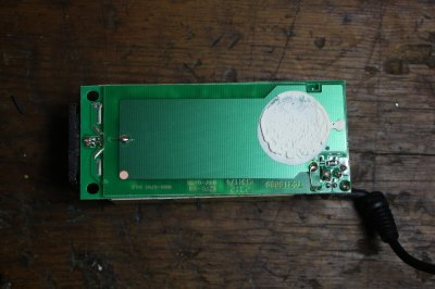
For [Peter]’s entry for the 2015 Hackaday Prize, he’s attempting to improve the standard industrial process to fix atmospheric nitrogen. Why? Fertilizers. He’s come up with an interesting technique that uses acoustic transducers in a pressure vessel, and to power that transducer, he’s turned to the greatest scrap heap in the world: eBay. He found a cheap ultrasonic power supply, but didn’t know offhand if it would work with his experiments. That’s alright; it’s a great opportunity to demo some basic reverse engineering skills.

A few months ago, [Dave Jones] posted a great video where he reverse engineers the front end of the new Rigol Zed. The basic technique is to make a photocopy, get some transparency sheets, grab a meter, and go to town. [Peter]’s technique is similar, only he’s using digital image manipulation, Photoshop, and a meter.

The process begins by taking pictures of both sides of the board, resizing them, flipping one side, and making an image with several layers. The traces on the bottom of the board were flooded and filled with the paint bucket tool, and components and traces carefully annotated.

With some effort, [Peter] was able to create a schematic of his board. He doesn’t know if this power supply will work with his experiments; there’s still some question of what some components actually do. Still, it’s a good effort, a great learning opportunity, and another log in [Peter]’s entry to The Hackaday Prize

The Modular Bench Power Supply To Rule Them All

Right now, [The Big One] is using an ATX power supply as a bench power supply for all his electronics projects. It works, but it’s not ideal. The next step up from a power supply from an old computer is, in order, one of those Chinese deals on Amazon, a used HP supply, or for the very cool people among us, building your own. [The Big One] is very, very cool and he’s building the modular bench supply to rule them all.

This is not your $100 china special power supply that [The Big One] would have to buy again in a few months. Inside this massive power supply is a massive transformer and rectifier that fans out to multiple power supply modules. The modules themselves will be based on an OPA548 that will be able to supply up to 3A with current limiting.

Each of these channels will be controlled by an ATMega32u4, with all the fancy stuff you’d expect from the ultimate supply; USB for setting voltage, current, and logging data, a nice LCD character display, and it’s surprisingly cheap; just about $100 for the transformer, and about $50 for each module.

It’s shaping up to be a great build, and with all the features, a power supply that would also make a great kit. If you have any input you’d like [The Big One] to hear, let him know on the project page.

A Primer On Buck (and Boost) Converters

We all know that the reason the electrical system uses alternating current is because it’s easy to step the voltage up and down using a transformer, a feature which just isn’t possible with a DC system… or is it? Perhaps you’ve heard of mysterious DC-DC transformers before but never really wanted to look at the wizardry that makes them possible. Now, SparkFun Director of Engineering [Pete Dokter] has a tutorial which explains how these mysterious devices work.

Known as buck converters if they step the input voltage down and boost converters if they step the voltage up, [Pete] explains how these circuits exploit the properties of an inductor to resist changes in current flow. He goes into exquisite detail to explain how components like transistors or MOSFETs are used to switch the current flow to the inductor very rapidly, and just exactly what happens to the magnetic field which makes these devices possible.

The video gives a good amount of background knowledge if you’ve always wanted to understand these devices a little bit better. There are also a few projects floating around that exploit these devices, such as one that uses an AVR microcontroller to perform the switching for a small circuit, or another that uses the interesting properties of these circuits to follow the I-V curve of a solar panel to help charge a bank of batteries. The possibilities are endless!

Continue reading “A Primer On Buck (and Boost) Converters”

A low cost power supply unit with displays

A Low Cost Bench Supply

Everyone needs a power supply on their bench, but a standard lab supply isn’t cheap. [ludzinc]’s PSU Console is a cheap alternative, which provides the basic features you’d expect in a lab supply.

The basis of this PSU is a DC/DC module based on the LM2596 step down switching regulator. These modules cost less than a single LM2596, but have all the required components for a buck DC/DC converter. Sure, they might not last forever, and they’re not the most efficient regulators, but the price is right.

The front panel has four displays for voltage and current, which are just low cost voltmeter displays. The potentiometers are used for adjusting the voltage of the DC/DC, and controlling the current limiter. This limiter monitors current through a shunt, and shuts off a MOSFET when the limit is exceeded.

The final product looks like something that’s ready for daily use, and was much cheaper than most supplies with these features. These low cost DC/DC modules are worth a look if you’re considering a similar build.

diy ATX power supply

Is This Power Supply Bigger Than A Bread Box? No, It Is One.

[newtonn2] must have had food on his mind when he was deciding to embark on a power supply project. The enclosure is quite different…. it is a Bread Box! Even so, flipped up on end we must say it looks pretty cool. [newtonn2’s] previous power supply had crapped out and he needed a replacement supply ASAP, it was a loaf or death situation for this electronics enthusiast.

Similar to a lot of DIY bench power supplies, this one would also be based on an ATX computer power supply. These are good high-current supplies that output voltage in several convenient amounts and in this case are are all routed to their own spring terminals mounted on the enclosure. Even though those standard voltages might be good enough for most, [newtonn2] is extremely kneady and wanted a fully adjustable output so he designed up an adjustable voltage regulation circuit using an LM350 regulator. A volt meter and an amp meter indicates the power being supplied on the adjustable circuit.

Since his last power supply was toast, [newtonn2] wanted this one to be easily repairable. The ATX power supply inside can be replaced in two minutes because nothing is hard wired. The only connections are the ATX connector and power cord. For cooling, holes were drilled in the side of the enclosure so that fans could be installed. This was the yeast he could do to keep the temperature of the interior components down.

In the end [newtonn2] completed his goal of building a pretty unique and functional bench top power supply without spending a lot of dough. Check out his Instructable for extremely detailed build instructions including schematics for how all his components are wired.

Joule Thief Steals Power For A Clock

A common project among electronics tinkerers is the joule thief, a self-oscillating circuit that can “steal” the remaining energy in a battery after the voltage has dropped so low that most devices would stop working. Typically the circuit powers an LED until almost all of the energy is extracted from the battery, but [Lionel Sears] has created a specialized joule theif that uses the “extra” energy to power a clock.

The circuit uses four coils instead of the usual two to extract energy from the battery. The circuit charges a large capacitor which provides the higher current pulses needed to drive the clock’s mechanism. It can power the clock from a single AA battery, and will run until the voltage on the battery is only 0.5 volts.

Normally the clock would stop running well before the voltage drops this low, despite the fact that there’s still a little chemical energy left in the batteries. The circuit can drive the clock for an extended time with a new battery, or could use old “dead” batteries to run the clock for a brief time while the final little bit of energy is drawn from them. If you’re so inclined, you could even use hot and cold water with a joule thief to run your clock! Thanks to [Steven] for the tip.

Hackaday Links, September 14, 2014

Photonicinduction is back! The Brit famous for not setting his attic on fire has built a 20,000 Watt power supply. It connects directly to England’s national grid with huge connectors. Impeccable fabrication and triple servo controlled variacs, and apparently this will be used for making a lot of hydrogen and oxygen through electrolysis of water.

In case you missed it, there’s a group buy for Flir’s Lepton thermal imaging module. Here’s the breakout board.

Need to solder something away from an outlet, and all you have is a disposable lighter? There’s a fix for that.

A Raspberry Pi case designed to be compatible with Lego. Now we need a hat/shield for NXT connectors.

Need another channel in your RC remote? Here’s this. It uses the gyro gain channel on a receiver. If someone wants to figure out how this works, wee do have a rather cool project hosting site.

0x06 0x1f1 CHSJOXWA OM YUFJPAI XFADBLY GIKQB CRZ MIXRB JRWV NN LZVOD XRI TBJKKVX MYYGID BLS LWNY XJVS FJO PYXBM MW D ELX ZG BIM CWMG JF PKI TKI ESZ WBME LKNLI BL 1407981609

Here’s something impossibly cool: The Macintosh PowerBop. It’s a Powerbook 170 with the floppy drive replaced with the radio in a cordless phone. It was part of France’s BiBop network, and you could buy private base stations for use at home. It is technically possible to use the radio as a wireless link to a modem, but [Pierre] couldn’t get PPP or a sufficiently ancient browser working. Plus ten points for taking it to an Apple store, and another twenty for trying to connect to our retro edition.

Chicken Lips. [Fran] and our very own [Bil Herd] are hanging out a bunch and recalling [Bil]’s time at Commodore. For this little featurette, [Bil] brought out his very own Commodore LCD. There are three of those in the world. Also included: tales of vertical integration, flipping bits with photons, and 80s era ERC.