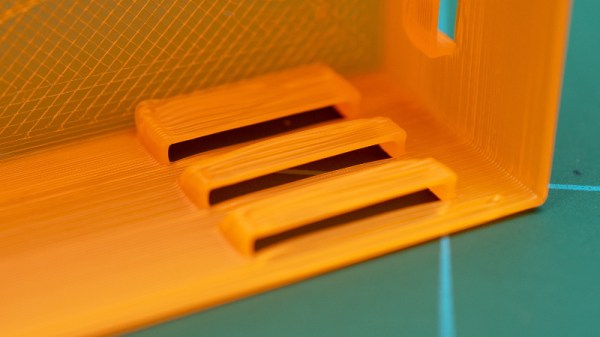
[Anton Gaia]’s SPIRAL sculpture resembles an organizer or modern shelving unit, but what’s really interesting is how it goes together. It’s made entirely from assembling copies of a single component (two, if you count the short ‘end pieces’ as separate) without a fastener in sight. [Anton] made the 3D model available, so check it out for yourself!

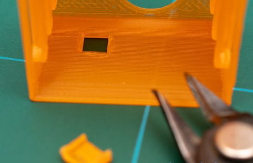
The ends of each part form a tight, spiral-shaped joint when assembled with its neighbors. Parts connect solely to themselves without any need of fasteners or adhesives.
The end result is secure, scalable, and with a harmonious structure that is very pleasing to look at. Small wonder [Anton] used it as the basis for artistic work. You can see more pictures here.
The design of the joint is based on the golden spiral (which it turns out is also a pretty useful chicken coop architecture.)
The parts lend themselves quite well to 3D printing, and we’d like to take a moment to appreciate that [Anton] shared the .step file instead of just an STL. STEP (or STP) files can be imported meaningfully into CAD programs, making it much easier to incorporate the design into one’s own work. STEP is also supported natively in many 3D printer slicers, so there’s no need to convert formats just to print them.
A brief video describing SPIRAL is embedded just below, with a closer look at how the pieces fit together.
Continue reading “Spiral Connector Makes Fastener-Free Assemblies”