Can you buy a working radar module for $12? As it turns out, you can. But can you make it output useful information? According to [Mathieu], the answer is also yes, but only if you ignore the datasheet circuit and build this amplification circuit for your dirt cheap Doppler module.
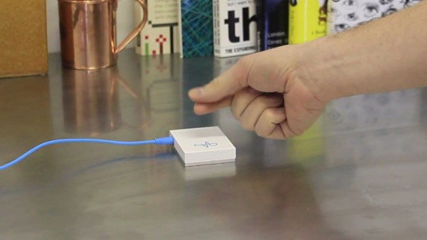
The module in question is a CDM324 24-GHz board that’s currently listing for $12 on Amazon. It’s the K-band cousin of the X-band HB100 used by [Mathieu] in a project we covered a few years back, but thanks to the shorter wavelength the module is much smaller — just an inch square. [Mathieu] discovered that the new module suffered from the same misleading amplifier circuit in the datasheet. After making some adjustments, a two-stage amp was designed and executed on a board that piggybacks on the module with a 3D-printed bracket.
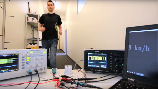
Frequency output is proportional to the velocity of the detected object; the maximum speed for the sensor is only 14.5 mph (22.7 km/h), so don’t expect to be tracking anything too fast. Nevertheless, this could be a handy sensor, and it’s definitely a solid lesson in design. Still, if your tastes run more toward using this module on the 1.25-cm ham band, have a look at this HB100-based 3-cm band radio.
Continue reading “The Right Circuit Turns Doppler Module Into A Sensor”

 Just a science curiosity, right? Maybe today, but not always. The story of these devices runs through World War II and is an object lesson in how new technology requires new ways of thinking about things.