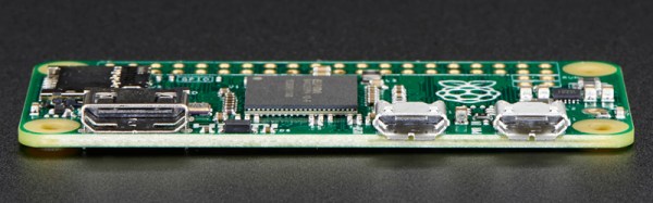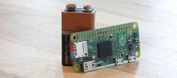
[gbaman] has figured out a simpler way to program the new Raspberry Pi Zero over USB without modifying the board. Why is this useful? One example which appealed to us was setting the Zero’s USB port up as a mass storage device. Imagine plugging in your Pi powered robot, dragging and dropping a Python script into the mass storage device that shows up, and pressing a button on the robot to run the new script. Pretty fancy for $5.00.
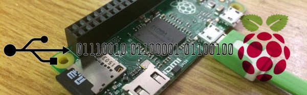
You can get the PI to emulate a whole range of devices from a USB MIDI controller to a simple USB serial interface. We’re excited to see what uses people come up with. Unfortunately the Pi Zero is still out of stock most everywhere as we wait for the next production run to finish. Though if you’ve got one, why not check out a few of our thoughts and experiences with the device!
[gbaman] based his work off the work done by [Dave-0] and others over at the Raspberry Pi forums. [LadyAda] also has a version of this hack, which we covered, that involves soldering a header to the pi and using a UART adapter.
[via Hacker News]