I had a small project going on–never mind exactly what–and I needed to detect a magnet. Normally, that wouldn’t be a big problem. I have a huge hoard of components and gear to the point that it is a running joke among my friends that we can be talking about building something and I will have all the parts we need. However, lately a lot of my stuff is in… let’s say storage (again, never mind exactly why) and I didn’t have anything handy that would do the job.
Options
If I had time, there are plenty of options for detecting a magnet. Even if you ignore exotic things like SQUID (superconducting quantum interference device) there’s plenty of ways to detect a magnet. One of the oldest and the simplest is to use a reed switch. This is just a switch made with a thin piece of ferrous material. When a magnet is nearby, the thin piece of metal moves and makes or breaks the contact.
These used to be common in alarm systems to detect an open or closed door. However, a trip to Radio Shack revealed that they no longer carry things like that as–apparently–it cuts into floorspace for the cell phones.
I started to think about robbing a sensor from an old computer fan or some other consumer item with a magnetic sensor onboard. I also thought about making some graphene and rolling my own Hall effect sensor, but decided that was too much work.
Browsing
I was about to give up on Radio Shack, but decided to skim through the two cabinets of parts they still carry just to get an idea of what I could and could not expect to find in the future. Then something caught my eye. They still carry a wide selection of relays. (Well, perhaps wide is too kind of a word, but they had a fair number.) It hit me that a relay is a magnetic device, it just generates its own electromagnetic field to open and close the contacts.
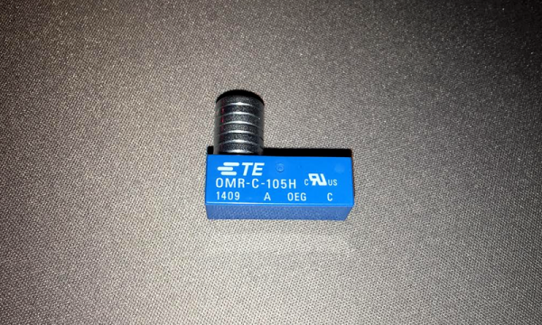
I picked up a small 5 V reed relay. They don’t show it online, but they do have several similar ones, so you can probably pick up something comparable at your local location. I didn’t want to get a very large relay because I figured it would take more external magnetic field to operate the contacts. You have to wonder why they have so many relays, unless they just bought a lot and are still selling out of some warehouse. Not that relays don’t have their use, but there’s plenty of better alternatives for almost any application you can think of.
Continue reading “Sensing A Magnet With Local Sourcing” →


 [Sprite_TM] also helped out with some
  Fail of the Week is a Hackaday column which celebrates failure as a learning tool. Help keep the fun rolling by writing about your own failures and


