The “Crivit Sports” is an inexpensive chest-strap monitor that displays your current pulse rate on a dedicated wristwatch. This would be much more useful, and presumably more expensive, if it had a logging option, or any way to export your pulse data to a more capable device. So [RoGeorge] got to work. Each post of the (so-far) three-part series is worth a read, not the least because of the cool techniques used.
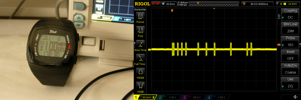
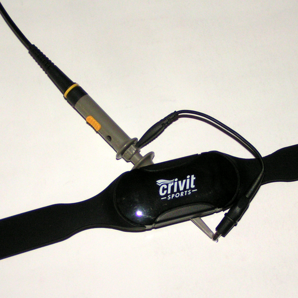 In part one, [RoGeorge] starts out by intercepting the signals. His RF sniffer? An oscilloscope probe shorted out in a loop around the heart monitor. Being able to read the signals, it was time to decode them. Doing pushups and decoding on-off keyed RF signals sounds like the ideal hacker training regimen, but instead [RoGeorge] used a signal generator, clipped to the chest monitor, to generate nice steady “heartbeats” and then read the codes off the scope without breaking a sweat.
With the encoding in hand, and some help from the Internet, he tested out his hypothesis in part two. Using an Arduino to generate the pulses logged in part one, he pulsed a coil and managed to get the heart rates displayed on the watch.
Which brings us to part three. What if there were other secrets to be discovered? Brute-forcing every possible RF signal and looking at the watch to see the result would be useful, but doing so for 8,192 possible codes would drive anyone insane. So [RoGeorge] taught himself OpenCV in Python and pointed a webcam at the watch. He wrote a routine that detected the heart icon blinking, a sign that the watch received a valid code, and then transmitted all possible codes to see which ones were valid. Besides discovering a few redundant codes, he didn’t learn much new from this exercise, but it’s a great technique.
We’re not sure what’s left to do on the Crivit. [RoGeorge] has already figured out the heart-rate data protocol, and could easily make his own logger. We are sure that we liked his thorough and automated approach to testing it all, from signal-generator-as-heartbeat to OpenCV as feedback in a brute-force routine. We can’t wait to see what’s up next.