Fans of [Ben Heck] know that he has a soft spot for pinball machines and his projects that revolve around that topic tend to be pretty epic. This is a good example. At a trade show he saw an extra-wide format LCD screen which he thought would be perfect on a pinball build. He found out it’s a special module made for attaching to your car’s sun visor. The problem is that it only takes composite-in and he wanted higher quality video than that offers. The solution: reverse engineer the LCD protocol and implement it in an FPGA.
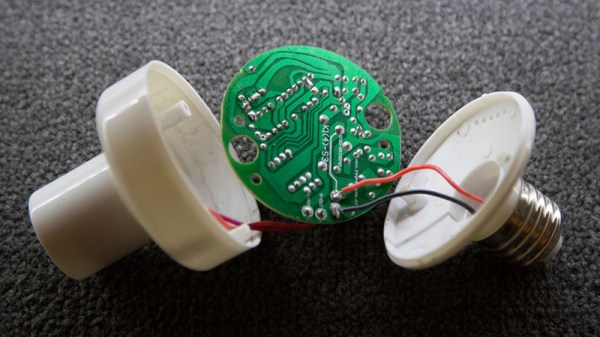
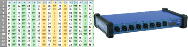
This project is a soup to nuts demonstration of replacing electronics drivers; the skill is certainly not limited to LCD modules. He starts by disassembling the hardware to find what look like differential signaling lines. With that in mind he hit the Internet looking for common video protocols which will help him figure out what he’s looking for. A four-channel oscilloscope sniffs the signal as the unit shows a blue screen with red words “NO SIGNAL”. That pattern is easy to spot since the pixels are mostly repeated except when red letters need to be displayed. Turns out the protocol is much like VGA with front porch, blanking, etc.
With copious notes about the timings [Ben] switches over to working with a Cyclone III FPGA to replace the screen’s stock controller. The product claims 800×234 resolution but when driving it using those parameters it doesn’t fill the entire screen. A bit more tweaking and he discovers the display actually has 1024×310 pixels. Bonus!
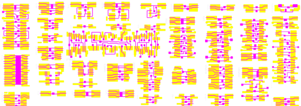
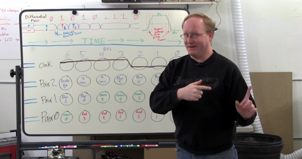
It’s going to take us a bit more study to figure out exactly how he boiled down the sniffed data to his single color-coded protocol sheet. But that’s half the fun! If you need a few more resources to understand how those signals work, check out one of our other favorite FPGA-LCD hacks.
Continue reading “Reverse Engineer Then Drive LCD With FPGA”