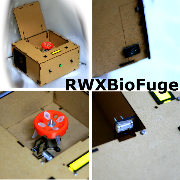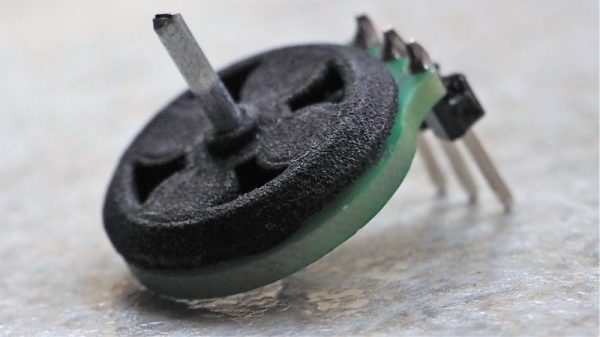
Mounting a motor on a PCB is nothing new, right? But how about making the PCB itself part of the motor? That’s what [Carl Bugeja] has done with his brushless DC motor in a PCB project, and we think it’s pretty cool.
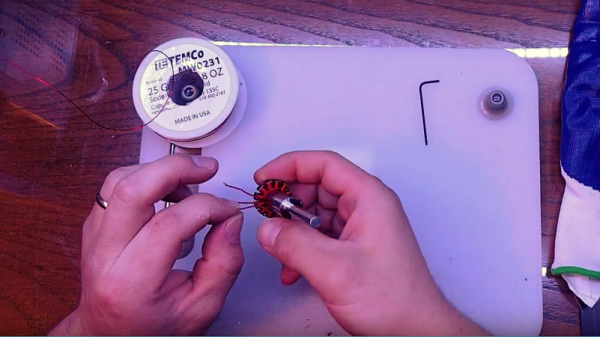
Details on [Carl]’s Hackaday.io page are a bit sparse at this point, but we’ve been in contact with him and he filled us in a little. The PCB contains the stator of the BLDC and acts as a mechanical support for the rotor’s bearing. There are six spiral coils etched into the PCB, each with about 40 turns. The coils are distributed around the axis; connected in a wye configuration, they drive a 3D-printed rotor that has four magnets pressed into it. You can see a brief test in the video below; it seems to suffer from a little axial wobble due to the single bearing, but that could be handled with a hat board supporting an upper bearing.
We see a lot of potential in this design. [Carl] mentions that the lack of cores in the coil limit it to low-torque applications, but it seems feasible to bore out the center of the coils and press-fit a ferrite slug. Adding SMD Hall sensors to the board for feedback would be feasible, too — in fact, an entire ESC and motor on one PCB could be possible as well. [Carl] has promised to keep the project page updated, and we’re looking forward to more on this one.
For a more traditional approach to printed motors, check out this giant 3D-printed BLDC.

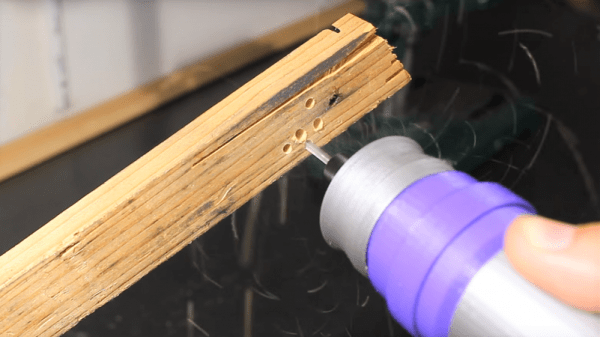
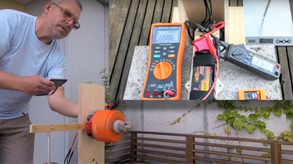

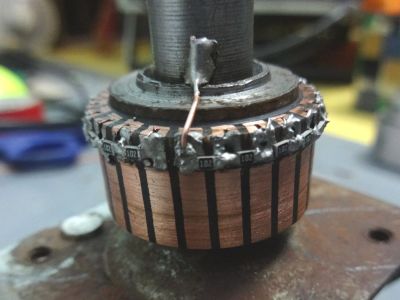 We have to admit that when we first saw [Ajoy Raman]’s Instructables post, we figured that he used a universal motor to generate a voltage from the anemometer. But [Ajoy]’s solution to the coaxial shafts problem is far more interesting than that. A discarded universal motor donated its rotor and bearings. The windings were stripped off the assembly leaving nothing but the commutator. 1kΩ SMD resistors were soldered across adjacent commutator sections to form a series resistance of 22kΩ with taps every 1k, allowing 0 to 2.2V to be read to the ADC of a microcontroller depending on the angle of the vane.