Mustachioed Rover Simultaneously Manly, Adorable

[Rick], an Adafruit learning system contributor, is excited by the implications of STEM’s reach into K-12 education. He was inspired to design Red Rover, a low-cost robot that can be easily replicated by anyone with access to a 3-D printer.
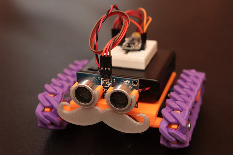
This adorable autonomous rover is based on the adafruit Trinket microcontroller, but will also rove under the power of an Arduino micro. It really is quite simple—the Trinket drives two continuous rotation micro servos and pretty much any flavor of rangefinder you like. [Rick] tested it with Parallax PING))), Maxbotix, and Grove sensors, and they all worked just fine.

What’s truly awesome about Red Rover are the track treads. [Rick] initially experimented with flexible filament. While he had good results, it was not a cost-effective solution. What you see in the picture and the short video after the break are actually rubber bracelets from Oriental Trading.

The plastic part count comes in at seven, all of which can be printed together at once. [Rick]’s gallery includes both small and large chassis and three different servo mounts. The Red Rover guide builds on other adafruit guides for Trinket general use, servo modification, and Trinket-specific servo control.

Update: Added [Rick]’s demo video after the break!

Continue reading “Mustachioed Rover Simultaneously Manly, Adorable”

Wireless Rover With Android Control

android-rover

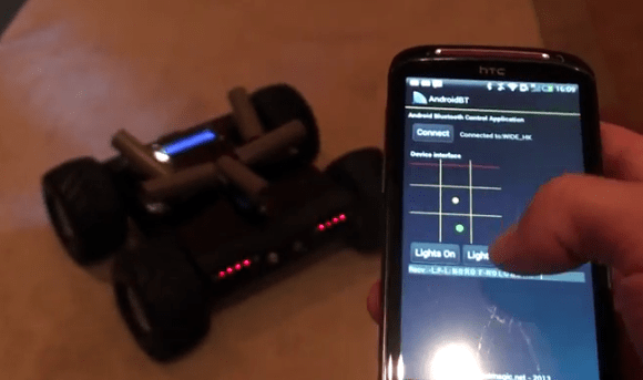
[Radu] spend the first portion of this year building and improving upon this wireless rover project. It’s actually the second generation of an autonomous follower project he started a few years back. If you browse through his old postings you’ll find that this version is leaps and bounds ahead of the last.

He purchased the chassis which also came with the gear-head motors and tires. Why reinvent the wheel (har har) when you’ve got bigger things on your plate? To make enough room inside for his own goodies he started out by ditching the control board which came with the Lynxmotion chassis in favor of an AVR ATmega128 development board. He also chose to use his own motor controller board. Next he added a metal bracket system to hold the battery pack. Things start to get pretty crowded in there when he installed his own Bluetooth and GPS modules. Rounding out his hardware additions were a set of five ultrasonic sensors (the grey tubes on top), a character display, as well as head and tail lights. The demo video shows off the control app he uses. We like that tic-tac-toe design for motion control, and that he added in buttons to control the lights.

Continue reading “Wireless Rover With Android Control”

GSM Controlled Car Without Needing A Microcontroller

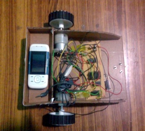
Nope, no microcontroller here, just a full-blown cellphone used as the brains of this little robot. The secret behind how it works is in the sounds the phone makes. The touch tones, known as DTMF, are monitored by the circuit mounted on the front half of the chassis and are responsible for driving the motors.

[Achu Wilson] built the circuit around an MT8870 chip which decodes the DTMF sounds and uses the BCD output to feed some logic chips. A 4 line to 16 line decoder and an inverter chip format the signals for use as inputs to the L293D motor driver. The video after the break shows him driving the rover directly by pressing number on the phone (like a tethered remote control). But he mentions that it’s possible to call the phone and press the numbers remotely. We assume you need to connect the call manually as we see no way to automatically answer calls.

This is certainly a fun way to play around with the DTMF protocol.

Continue reading “GSM Controlled Car Without Needing A Microcontroller”

Arduino Rover Evolves To A Trike Design

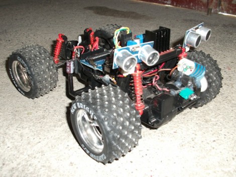
[Eduard Ros] wrote in to show off the latest version of his Arduino powered autonomous rover (translated). You may remember seeing the first version of the build back in June. It started with a remote control truck body, adding an Arduino and some ultrasonic sensors for obstacle avoidance.

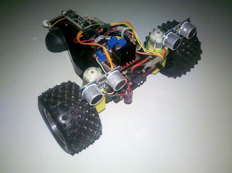
The two big wheels and the pair of sensors look familiar, but most of the other components are a different from that version. The biggest change is the transition from four wheels to just three. This let him drop the servo motor which controlled steering. At first glance we though this thing was going to pop some mad wheelies, but the direction of travel actually drags the third wheel being the larger two. The motors themselves are different, this time depending on gear-reduced DC motors. The motor H-bridge is the same, but [Eduard] used a simple transistor-based inverter to reduce the number of pins needed to activate it from two down to just one. He also moved from an Arduino Uno to a Nano to reduce the footprint of the controller.

Arduino Rover Doubles Up On Obstacle Avoidance

[Eduard Ros] wrote in show off his first attempt at building an autonomous rover (translated). As with many of these projects, he started with the base of a remote control toy truck. This solves so many mechanical issues, like steering, locomotion, and power source.

He just needed a way to control the vehicle. The recent LayerOne badge hacks either did this through the wireless controller protocol or by adding an Arduino directly to the vehicle. [Eduard] chose the latter, and also included obstacle avoidance sensors in the process. We’ve seen quite a few that use these ultrasonic rangefinders. He decided to go a different route by adding two of them rather than scanning by mounting one on a servo motor.

The video after the break shows the vehicle successfully navigating through a tight space. This makes us wonder how much data can be processed from the stationary sensors? We’re not familiar with how wide the horizontal sensitivity is on the devices. If you have some insight, please share you knowledge in the comments section.

Continue reading “Arduino Rover Doubles Up On Obstacle Avoidance”

CalTech’s Manipulator-arm Equipped Robot

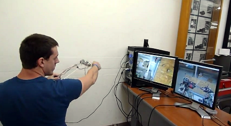
[Justin] wrote in to tell us about the rover which his CalTech team has entered in NASA’s Exploration Robo-Ops Competition. Their time to shine is later this week, but you can see some of the test footage after the break.

The operator pictured above is using a controller which is a scale model of the manipulator arm, with two cameras giving feedback. One of those monitors shows a feed from the arm itself, providing a view of the gripper. The other feed is a wide shot of the working area from the body of the robot. The arm has six degrees of freedom actuated by servo motors. The controller is a replica of the arm laser cut from acrylic. At each joint there’s a potentiometer whose value is used to establish the position of the frame.

At first we thought that this would be more fatiguing and less convenient than using a gaming controller. But as we look at the dexterity of the arm it becomes obvious that joysticks and buttons would just make things more difficult.

Continue reading “CalTech’s Manipulator-arm Equipped Robot”

There’s A Lot Packed Into This BeagleBoard Controlled Rover

That black box is hiding all kinds of goodies that make this rover a hacking playground. [Andrey] built the device around a BeagleBoard, which offers the processing power and modules that he needed to make the rest of it work.

The control unit shrinks the pilot down to the rover’s size, using a cockpit that has a steering wheel and other controls, and a monitor playing the stream from the camera on the front of the bot. It has a WiFi adapter which allows control via the Internet. The camera, which can be rotated thanks to its servo mounting, feeds the video to the BeagleBoard where it is compressed using the h264 codec (more about that and the cockpit here) to lighten the streaming load. You’ll also find an ultrasonic rangefinder on the front for obstacle avoidance, and a magnetic compass for orientation information. Finally, a GPS bolsters that data, allowing you to plot your adventures on the map.

It’s great, but it will cost you. Material estimates are North of five hundred Euros!