Towards DIY Flip Digit Clocks

Seven segment displays and Nixies are one thing, but the king of all antique display technologies must be electromechanical flip dots. These displays, usually found in train stations or rarely on old bus lines, are an array of physical disks, black on one side, light on the other, that ‘flip’ back and forth with the help of an electromagnet. They’re expensive and impressive, driving them is a pain, but oh man do they look awesome.

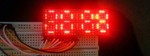
While flip dot displays can be bought new if you know where to look, [sjm4306] had the idea to build his own out of inexpensive materials. It might just be a prototype, but we’re saying he’s succeeded. He has the workings of a seven flip-segment display, and the techniques he’s using mean it shouldn’t be too expensive to build your own.

Instead of building a matrix of flip dots, [sjm] is building a mechanical seven-segment display. Each of the segments are 3D printed in black PLA, and mounted to a piece of cardboard via a thin wire ‘axel’ going through the length of the segment. Where normal flip dots use an electromagnet to change each dot from one state to another, [sjm] mounted a very small vibrating pager motor to one end of the segment. When one half of a tact switch h-bridge is activated, the segment flips to the front. When the other half of the h-bridge is activated, the segment flips back.

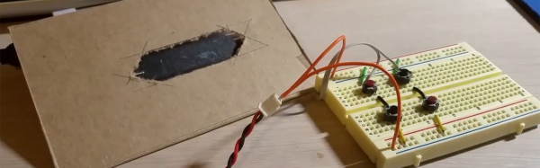
Right now, this hardware is in the ‘extreme prototype’ stage, but results so far are encouraging. [sjm] has already designed a single-segment ‘module’. Plans for the electronics include optocouplers for two microcontroller pins for each segment and reed relays for each individual digit. For a four-digit display, these flip digits will only require 18 I/O pins.

You can check out [sjm4306]’s video for this project below. It’s a little bit long, but watch those things flip!

Continue reading “Towards DIY Flip Digit Clocks”

Panel Mount Display Solves The Problem Of Drilling Square Holes

[Absolutelyautomation] has a problem with seven-segment displays. Fitting these displays in an enclosure is a pain because you can’t drill perfectly square holes, and you will invariably mess up a few enclosures with overzealous file work. There is a solution to this problem – panel mount meters.

The bezels on these panel mount meters hide the imperfections in the enclosure, and usually don’t require screws. They are, however, dedicated displays, usually for temperature, RPM, or some other measurement.

[Absolutelyautomation] took one of these dedicated panel mount displays and turned it into an all-purpose device. Basically, it’s a panel mount Arduino with three seven-segment displays.

This project is built on perfboard cut down to fit inside the enclosure of a very cheap panel meter found at the usual suppliers. Tucked away underneath this perfboard is an ATmega, a few resistors, and the support parts to make everything go. This panel mount meter can either be a serial slave or as a standalone controller, programmable with the Arduino IDE. It’s cheap, too. You can check out [Absolutelyautomaion]’s video below.

Continue reading “Panel Mount Display Solves The Problem Of Drilling Square Holes”

An 840 Segment Display

A while back, [limpfish] bought a few four-digit seven-segment displays from a seller on eBay. A month or two later, thirty displays ended up in [limpfish]’s mailbox. Instead of using the one or two displays he thought he ordered, [limpfish] decided to do something very cool with these bits of seven-segment displays. He’s controlling all of them at once.

[limpfish]’s usual method of controlling a lot of LEDs is the MAX7219 LED driver. This chip can easily — and cheaply — control eight common cathode seven segment displays. There’s a problem with this plan, though: the LEDs received from eBay are common anode. That’s actually not a problem, because with a little effort and even more thinking [limpfish] got these displays to work with the MAX7219 driver chip.

With chips in hand, [limpfish] designed a small breakout board for the MAX7219 and two common anode 4×7 segment displays. These displays can be daisy chained, and connecting them all together results in a very weird but very cool visualization.

[limpfish] is treating this display as a bitmap display, which means it’s demo time. You can check out a 1337 01d skool demo playing on this 840-segment display in the video below.

Continue reading “An 840 Segment Display”

Puzzlingly Simple Tutorial On GPS Time Corrected Clock

We’re not sure if [Derek Lieber] is messing with us or proving a point. Why are you doing this [Derek]? We know there’s technically enough information to build the clock. You even included the code. Couldn’t you have at least thrown in a couple of words? Do we have to skip straight to mediaglyphics?

Anyway, if we follow the equation. The equation… If you take a gps module, a 7 segment display with an HT16K33 backpack, a digital potentiometer, a piezo, and a boarduino we suppose we could grudgingly admit that these would all fit together to make a clock. We still don’t like it though, but we’ll admit that the nice handmade case was a nice touch, and that the pictures do give us enough details to do it ourselves.

It was also pretty cool when you added the Zelda theme song as an alarm sound. Also pretty neat that, being GPS corrected, there’s no need to ever set the time. We may also like the simplicity of the only inputs being the potentiometer, which is used to set the alarm time. It’s just. Dangit [Derek]. Nice clock build, we like it.

Learning And Failing At Digital Electronics

[spencerhamblin] is starting his explorations into digital electronics the hard way: reproducing a “simple” IC’s functionality by wiring up a board full of discrete transistors. In this case, the end product is a binary-to-seven-segment decoder built from scratch.

In engineering circles, this circuit is better known as a 7447 BCD to seven-segment decoder/driver, but just using a single chip has little pedagogical value. Building a simple circuit with 39 transistors, 31 resistors, and a handful of diodes is a good introduction to digital electronics, and after two attempts, [spencerhamblin] knocked it out of the park.

The build began with a piece of copper clad board, a bunch of cheap FETs from fleabay, and an incorrect schematic. While the first version of the project looked fantastic with Manhattan-style construction, and jumper wires everywhere, the schematic was fundamentally flawed and [spencer] got a little confused when converting the circuit to a common anode display.

Version two used a more standardized construction. This circuit was plotted in DipTrace, and the resulting PCB was sent off to OSHPark. The build was cleaner, but in capturing the schematic, [spencer] reversed the footprint of the seven segment display. That was easy enough to fix with a few short wires, and after a little bit of work [spencer] had a device that would convert binary to a seven segment display.

Tiny PIC Clock Is Not A Tiny Bomb

It’s been a few weeks since the incident where Ahmed Mohamed, a student, had one of his inventions mistaken for a bomb by his school and the police, despite the device clearly being a clock. We asked for submissions of all of your clock builds to show our support for Ahmed, and the latest one is the tiniest yet but still has all of the features of a full-sized clock (none of which is explosions).

[Markus]’s tiny clock uses a PIC24 which is a small yet powerful chip. The timekeeping is done on an RTCC peripheral, and the clock’s seven segment displays are temporarily lit when the user presses a button. Since the LEDs aren’t on all the time, and the PIC only consumes a few microamps on standby, the clock can go for years on a single charge of the small lithium-ion battery in the back. There’s also a phototransistor which dims the display in the dark, and a white LED which could be used as a small flashlight in a pinch. If these features and the build technique look familiar it’s because of [Markus’] tiny MSP430 clock which he was showing around last year.

Both of his tiny clocks are quite impressive for their size, features, and power consumption. Some of the other clocks we’ve featured recently include robot clocks, clocks for social good, and clocks that are not just clocks (but still won’t explode). We’re suckers for a good clock project here, so keep sending them in!

Continue reading “Tiny PIC Clock Is Not A Tiny Bomb”

DIY Seven Segment Displays

[Esai] wanted to build an electronic clock from scratch. A noble quest, but ordinary seven-segment displays are just that – incredibly ordinary. Instead of a few displays that can be bought from the usual retailers for a dollar a piece, [Esai] made his own four digit, seven-segment display on some perfboard.

Before soldering 58 SMD LEDs to a small rectangle of perfboard, [Esai] traced out each segment with a marker. Two LEDs make up each segment, and they’re all connected to a breadboard-friendly pin header with 30 gauge wire.

Each segment is connected as a single column in the LED matrix, and each digit is a row. It’s a simple design, but there aren’t any resistors on this board. Hopefully [Esai] will be using a proper LED driver with this display; you really don’t want LEDs to burn out twice a day at 1:11.