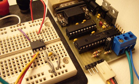
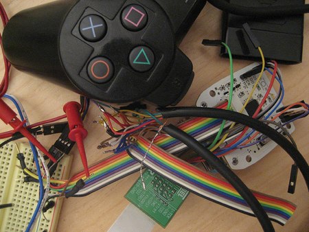
How-to: The Bus Pirate, Universal Serial Interface

UPDATE: New firmware with JTAG and more

We’re always excited to get a new chip or SIM card to interface, but our enthusiasm is often dampened by the prototyping process. Interfacing any chip usually means breadboarding a circuit, writing code, and hauling out the programmer; maybe even a prototyping PCB.

A few years ago we built the first ‘Bus Pirate’, a universal bus interface that talks to most chips from a PC serial terminal. Several standard serial protocols are supported at 3.3-5volts, including I2C, SPI, and asynchronous serial. Additional ‘raw’ 2- and 3- wire libraries can interface almost any proprietary serial protocols. Since this has been such a useful tool for us, we cleaned up the code, documented the design, and released it here with specs, schematic, and source code.

Continue reading “How-to: The Bus Pirate, Universal Serial Interface”

Tiny Arduino Ethernet Board

[sgk] built this tiny ethernet board to be used with the Arduino. It’s based on a WIZnet W5100 chip. The chip handles all of the TCP/IP communication and you talk to it via SPI. It’s compatible with the standard Arduino ethernet library. [sgk] hand soldered these boards including the 80pin LQFP main chip. His next project is to put the AVR and W5100 all on the same board. It sounds like he’ll use components larger than 1005 though.

Logicport Overview


As promised earlier, the Near Future Laboratory has published an overview of the Logicport Logic Analyzer. They’re using the Playstation 2 analysis as an example. The Logicport uses “interpreters” to define protocols. It has I2C/TWI, SPI, RS232, and CAN 2.0A/2.0B, but you can build your own interpreter based on these. You can specify bit order and the format you want the data in. Slave interpreters can be used for specific tasks: with the PS2 they were used to just show the fifth byte, which is the actual button press.

“Triggers” are used to signal specific activity. On the PS2, one was attached to the falling signal on the slave select line. This event means the master is about to start sending data.

The final area worth exploring is “measurements”. These can be frequency or arbitrary time intervals between events. The Logicport has multiple ground connections to eliminate noise from the signal and you’ll have to play with sample rate and logic level to get things running smooth. It’s nice to see how-tos written from the perspective of someone just getting started with the tool.

Playstation 2 Controller Analysis


The people at Near Future Laboratory are trying to spoof the behavior of a Playstation 2 controller using just a microcontroller. They wrote some initial code using the controller info found here, but decided the best way to figure out what was going on, was to probe the interface. They’re using a Logicport, which features 34 channels plus two clock channels. They only need six channels because the PS2 implements an SPI protocol plus an ACK line. The post is just a preliminary investigation, but will give you a little insight into how the Logicport works and why you might find it useful.