[Tom] sent this in to be filed under the ‘not a hack’ category, but it’s actually very interesting. It’s the User’s Guide for the Falcon 9 rocket. It includes all the data necessary to put your payload on a Falcon 9 and send it into space. It’s a freakin’ datasheet for a rocket.
A year ago in Japan (and last week worldwide), Nintendo released Pokkén Tournament, a Pokemon fighting game. This game has a new controller, the Pokkén Tournament Pro Pad. There were a few cost-cutting measures in the production of this game pad, and it looks like this controller was supposed to have force feedback and LEDs. If any Pokemon fans want to take this controller apart and install some LEDs and motors just to see what happens, there’s a Hackaday write up in it for you.
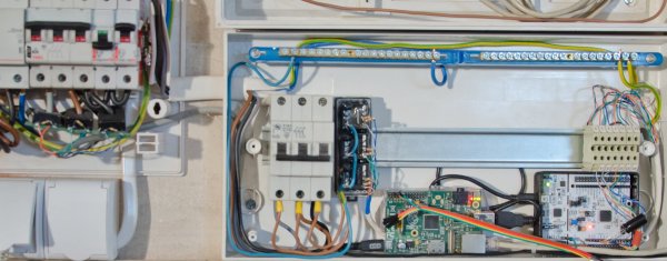
There are a lot of options for slicing 3D objects for filament-based 3D printers. Cura, Slic3r, and MatterControl are easily capable of handing all the slicing needs you’ll ever have for a filament 3D printer. For sterolithography (resin) printers, the options for slicing are limited. [skarab] just put together a new slicer for SLA that runs entirely in JavaScript. If anyone wants to turn a Raspi or BeagleBone into a network controller for a resin printer, here’s your starting point. [skarab] will be working on smoothieboard integration soon.
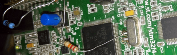
The STM32F4 is an extremely capable ARM microcontroller. It can do VGA at relatively high resolutions, emulate a Game Boy cartridge, and can serve as the engine control unit in a 1996 Ford Aspire. There’s a lot of computing power here, but only one true litmus test: the STM32F4 can run Doom. [floppes] built this implementation of Doom on the STM32F429 Discovery board to run off of an external USB memory stick. The frame rate is at least as good as what it was back in 1993.
The Oculus Rift has just come to pass, but one lucky consumer got his early. The first person to preorder the Rift, [Ross Martin] of Anchorage, Alaska, got his facehugger directly from [Palmer Luckey] in a PR stunt on Saturday afternoon. Guess what [Ross] is doing with his Rift?