It’s pretty well known by now that the LED pixel hardware which is starting to be commonplace, both WS2811 and WS2812, needs pretty strict timing in order to address them. There are libraries out there which mean almost no work on your part, but that’s no fun. [Elia] started looking into what it takes to drive the hardware, trying out a few 8-bit micros before moving to 32-bit with the help of an STM32VL Discovery Board. The move to a beefier processor brings a lot of speed, but why bit bang everything? He came up with a way to use the PWM and DMA features of the chip to drive the LEDs.
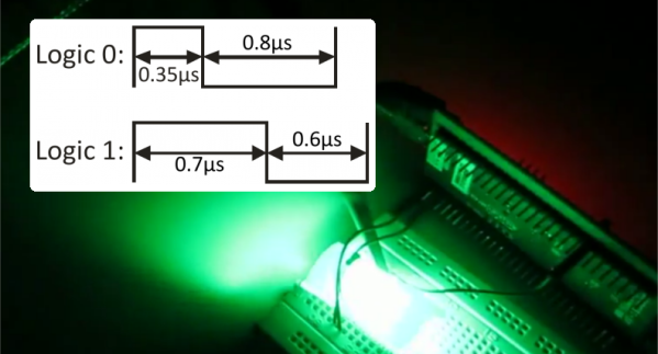
DMA is the Direct Memory Access unit that allows you to change the values being sent to the pixel without interrupting the processor. This is done by pre-loading the data at a memory location. This buffer is automatically read by the DMA unit — its values are used to set the PWM timer compare trigger in order to send out logic values show in the diagram above.
If you do want to delve further into this topic here’s a collection of techniques for driving the WS2811.