How A Hacker Jump Starts A Car

Here’s the Scenario: you need to get somewhere in a hurry. The problem is that your car has a dead battery and won’t turn over. The Obvious solution would be to call a friend for a jump. But is the friendless hacker out of luck in such a situation? Not if you can whip up a quick parts bin jump starter.

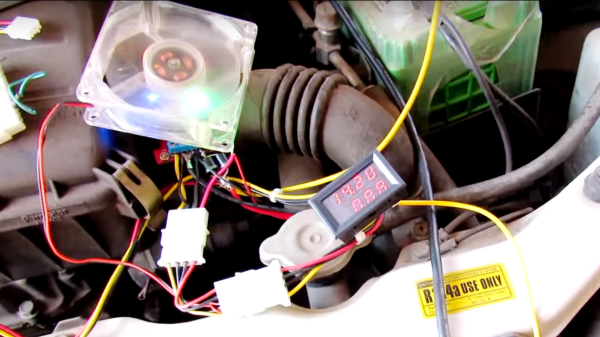
Clearly, [Kedar Nimbalkar]’s solution would be practical only under somewhat bizarre circumstances, so we’ll concentrate on what we can learn from it. A spare PC power supply provides the electrons – [Kedar]’s 250W supply pushes 15A at 12 volts, which is a pretty respectable amount of current. The voltage is a little anemic, though, so he pops it up to 14.2 volts with a 150W boost converter cooled with a PC fan. A dual panel meter reads out the voltage and current, but a VOM could substitute in a pinch. About the only thing you might not have on hand is a pair of  honking 10A diodes to keep current from creeping back into the boost converter. [Kedar] claims he got enough of a charge back in the battery in five minutes to start his car.

As jump-starting goes, this hack is a bit of a stretch. It’s not the first time we’ve seen a MacGyver’d jump starter, though, and you never know when the principles and hardware behind these hacks will come in handy.

Continue reading “How A Hacker Jump Starts A Car”

Hackaday Prize Entry: A 7805 Replacement

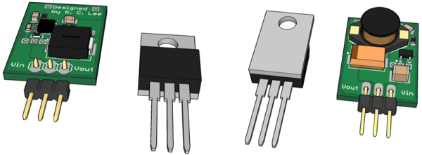
The 7805 voltage regulator is a great device if you want a simple way of bringing a voltage down to 5V. It’s a three-pin, one-component solution that puts out five volts and a lot of heat. Simple, not efficient. For his Hackaday Prize entry, [K.C. Lee] is working on a much more efficient drop-in replacement for the 7805.

Linear regulators like the 7805 are great, but they’re not terribly efficient. Depending on the input voltage you might see 50% efficiency. Going to a switch mode supply, that efficiency shoot up to about 90%.

For his drop-in replacement, [K.C. Lee] is using the LM3485, a switch mode regulator that only needs a few extra parts to turn it into a replacement for the 7805. You will need a cap on the input, but you should already be putting those in your circuit anyway, right?


The 2015 Hackaday Prize is sponsored by:

Emergency Power Based On Cordless Drill Batteries

[Don Eduardo] took matters into his own hands after experiencing a days-long power outage at his house. And like most of us have done at least one, he managed to burn his fingers on a regulator in the process. That’s because he prototyped a way to use power tool batteries as an emergency source — basing his circuit on a 7812 linear regulator which got piping hot in no time flat.

His next autodidactic undertaking carried him into the realm of switch-mode buck converters (learn a bit about these if unfamiliar). The device steps down the ~18V output to 12V regulated for devices meant for automotive or marine. We really like see the different solutions he came up with for interfacing with the batteries which have a U-shaped prong with contacts on opposite sides.

The final iteration, which is pictured above, builds a house of cards on top of the buck converter. After regulating down to 12V he feeds the output into a “cigarette-lighter” style inverter to boost back to 110V AC. The hardware is housed inside of a scrapped charger for the batteries, with the appropriate 3-prong socket hanging out the back. We think it’s a nice touch to include LED feedback for the battery level.

We would like to hear your thoughts on this technique. Is there a better way that’s as easy and adaptive (you don’t have to alter the devices you’re powering) as this one?

Continue reading “Emergency Power Based On Cordless Drill Batteries”

A Primer On Buck (and Boost) Converters

We all know that the reason the electrical system uses alternating current is because it’s easy to step the voltage up and down using a transformer, a feature which just isn’t possible with a DC system… or is it? Perhaps you’ve heard of mysterious DC-DC transformers before but never really wanted to look at the wizardry that makes them possible. Now, SparkFun Director of Engineering [Pete Dokter] has a tutorial which explains how these mysterious devices work.

Known as buck converters if they step the input voltage down and boost converters if they step the voltage up, [Pete] explains how these circuits exploit the properties of an inductor to resist changes in current flow. He goes into exquisite detail to explain how components like transistors or MOSFETs are used to switch the current flow to the inductor very rapidly, and just exactly what happens to the magnetic field which makes these devices possible.

The video gives a good amount of background knowledge if you’ve always wanted to understand these devices a little bit better. There are also a few projects floating around that exploit these devices, such as one that uses an AVR microcontroller to perform the switching for a small circuit, or another that uses the interesting properties of these circuits to follow the I-V curve of a solar panel to help charge a bank of batteries. The possibilities are endless!

Continue reading “A Primer On Buck (and Boost) Converters”