A Teardown Of Something You Should Not Own

GPS jammers are easily available on the Internet. No, we’re not linking to them. Nevertheless, GPS jammers are frequently used by truck drivers and other people with a company car that don’t want their employer tracking their every movement. Do these devices work? Are they worth the $25 it costs to buy one? That’s what [phasenoise] wanted to find out.

These tiny little self-contained boxes spew RF at around 1575.42 MHz, the same frequency used by GPS satellites in high Earth orbit. Those signals coming from GPS satellites are very, very weak, and it’s relatively easy to overpower them with noise. That’s pretty much the block diagram for these cheap GPS jammers — put some noise on the right frequency, and your phone or your boss’s GPS tracker simply won’t function. Note that this is a very low-tech attack; far more sophisticated GPS jamming and spoofing techniques can theoretically land a drone safely.

[phasenoise]’s teardown of the GPS jammer he found on unmentionable websites shows the device is incredibly simple. There are a few 555s in there creating low-frequency noise. This feeds a VCO with a range of between 1466-1590 MHz. The output of the VCO is then sent to a big ‘ol RF transistor for amplification and out through a quarter wave antenna. It may be RF wizardry, but this is a very simple circuit.

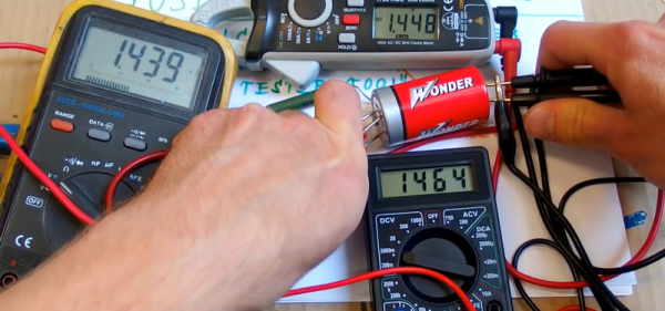
The output of this circuit was measured, and to the surprise of many, there were no spurious emissions or harmonics — this jammer will not disable your cellphone or your WiFi, only your GPS. The range of this device is estimated at 15-30 meters in the open, which is good enough if you’re a trucker. In the canyons of skyscrapers, this range could extend to hundreds of meters.

It should be said again that you should not buy or use a GPS jammer. Just don’t do it. If you need to build one, though, they’re pretty easy to design as [phasenoise]’s teardown demonstrates.

Glue Gun Teardown Reveals Microcontroller Mystery

[electrobob] got a Bosch GluePen cordless hot glue gun. The thing has some nice features — it heats up in fifteen seconds, and charges via USB, and is generally handy for those small and quick jobs that hot glue guns were made to perform. At first glance it seems like a huge improvement over the plug-in varieties, which seem to take forever to heat up when all you need is a quick dab of glue.

As cool as the product sounded, [bob] did what any right-minded hacker would do and opened it up to see how that sucker work and found an ATtiny24A inside. What’s most interesting is that there appears to be no temperature regulation or sensing capability, with the exception of the thermistor in the battery-charging circuit. It’s an intriguing mystery.

The ATtiny controls a power MOSFET that brings the heating element to “approximately 170 degrees” according to the manual. [bob] could find no temperature regulation of the hot end, which measures a steady 12 V at the gate of the transistor then entire time the glue gun is powered on.

That ATtiny24A that runs the whole thing packs 12 GPIO pins, 4 PWM channels, and 2 KB program memory. It appears a bit overpowered for a glue gun controller. [bob] found one of the Tiny’s pins connected the heating element and another to the charging circuit. Maybe a shutoff in case the battery catches fire?

Without a clear shot of the back of the board, it’s a bit of a guessing game, but eight of the twelve GPIO pins appear to be in use. Leave your theories in comments. And if you’ve got any bright ideas about what to do with the remaining four GPIO pins, have at it!

For another of [bob]’s tool hacks, check out his constant current sink we posted earlier this year.

Teardown Of A Cheap Glue Gun

A hot glue gun is one of those standard tools of the hardware hacker’s bench, called upon to provide adhesion between an astonishing range of materials, and to provide a handy filler and strain relief in the form of blobs of polymer glue. We’ve all got one, but how many of us have taken a look inside it?

[Andrew Lorimer] bought a super-cheap eBay glue gun, and subjected it to a teardown. As you might expect, he found it to be a pretty simple device with only a trigger mechanism and a dumb heating element, but his write-up is of passing interest because he’s characterised its heating element. It has a positive temperature coefficient, which means that its resistance increases from around 2.5 kΩ at room temperature to about 7 kΩ at its 150 ºC operating temperature. This limits the current, and provides a very simple thermostat action.

The build quality is surprisingly good for such a cheap appliance, and he notes a surfeit of screws holding its shell together. But the quality of the insulation and strain relief leaves a lot to be desired, and he wonders whether it truly qualifies for its double-insulated logo. The LED pilot light is simply fed from the 240 V mains supply through a 250 kΩ resistor which he replaces with a 12 kΩ component for a brighter result.

We cover plenty of teardowns here at Hackaday. Often they are of extremely expensive and complex devices, but sometimes they are of much simpler subjects.

Mike Harrison’s Reverse Engineering Workshop

Hardware teardowns are awesome when guided by experts. One of our favorites over the years has been [Mike Harrison], who has conquered teardowns of some incredibly rare and exquisitely engineered gear, sharing the adventure on his YouTube channel: mikeselectricstuff. Now he’s putting on a workshop to walk through some of the techniques he uses when looking at equipment for the first time.

[Mike] will be in Pasadena a few days early for the Hackaday Superconference and floated the idea of hosting a workshop. We ordered up some interesting gear which he hasn’t had a chance to look at yet. A dozen lucky workshop attendees will walk through the process [Mike] uses to explore the manufacturing and design choices — skills that will translate to examining any piece of unknown gear. He may even delve into the functionality of the equipment if time allows. Get your ticket right now!

To keep things interesting we’re not going to reveal the equipment until after the fact. But follow the event page where we’ll publish the details of his reverse engineering work after the workshop.

[Mike] is the badge designer for this year’s Hackaday Superconference badge. Unfortunately Supercon is completely sold out (we tried to warn you) but you can check out the badge details he already published. And we will be live streaming the Supercon this year — more details on that next week!

Horizontal Magnetic Levitation Experiments

Levitating chairs from the Jetsons still have a few years of becoming a commercial product though they are fun to think about. One such curious inventor, [Conor Patrick], took a deep dive into the world of maglev and came up with a plan to create a clock with levitating hands. He shares the first part of his journey to horizontal levitational control.

[Conor Patrick] bought an off-the-shelf levitation product that was capable of horizontal levitation. Upon dissecting it he found a large magnet, four electromagnet coils, and a hall effect sensor. These parts collectively form a closed-loop control to hold an object at a specific distance. He soon discovered that in fact, there were just two coils energized by H-bridges. His first attempt at replicating the circuit, he employed a breadboard which worked fine for a single axis model. Unfortunately, it did not work as expected with multiple coils.

After a few iteration and experiments with the PID control loop, he was able to remove unwanted sensor feedback as well as overshoot in control current. He finally moved to a Teensy with a digital PD loop. The system works, but only marginally. [Conor Patrick] is seeking help from the control loop experts out there and that is the essence of the OSHW world. The best part of this project is that it is a journey that involves solving one problem at a time. We hope to see some unique results in the future.

We have covered Acoustic Levitation in the past and the Levitating Clock on a similar beat. We’re certain a more refined approach is on the horizon since many of us are now looking at making one to experiment with on our workbench.

SCiO “Pocket Molecular Scanner” Teardown

Some of you may remember the SCiO, originally a Kickstarter darling back in 2014 that promised people a pocket-sized micro spectrometer. It was claimed to be able to scan and determine the composition of everything from fruits and produce to your own body. The road from successful crowdsourcing to production was uncertain and never free from skepticism regarding the promised capabilities, but the folks at [Sparkfun] obtained a unit and promptly decided to tear it down to see what was inside, and share what they found.

The main feature inside the SCiO is the optical sensor, which consists of a custom-made NIR spectrometer. By analyzing the different wavelengths that reflect off an object, the unit can make judgments about what the object is made of. The SCiO was clearly never built to be disassembled, but [Sparkfun] pulls everything apart and provides some interesting photos of a custom-made optical unit with an array of different sensors, various filters, apertures, and a microlens array.

It’s pretty interesting to see inside the SCiO’s hardware, which unfortunately required destructive disassembly of the unit in question. The basic concept of portable spectroscopy is solid, as shown by projects such as the Farmcorder which is intended to measure plant health, and the DIY USB spectrometer which uses a webcam as the sensor.

Inside A Microswitch

We’ve taken a few microswitches apart, mostly to fix those pesky Logitech mice that develop double-click syndrome, but we’ve never made a video. Luckily, [Julian] did, and it is worth watching if you want to understand the internal mechanism of these components.

[Julian] talks about the way the contacts make and break. He also discusses the mechanical hysteresis inherent in the system because of the metal moving contact having spring-like qualities

Continue reading “Inside A Microswitch”