It’s probably not much of a stretch to say that many of us have taken on a project or two that were little more than thinly veiled excuses to add a new tool or piece of gear to our arsenal. There’s something to be said for a bench full of button-festooned test equipment blinking away, it’s like bling for nerds. But just like getting your name written out in diamonds, it can get expensive quick.
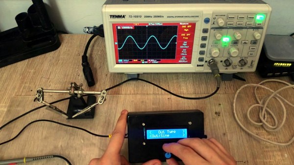
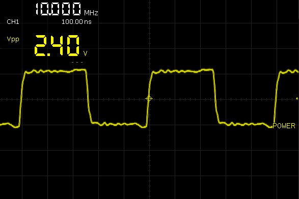
 Luckily, the hacker has enough technology at their disposal these days that DIY test equipment can help fill your bench without emptying your wallet. [Faransky] has created a very impressive Arduino function generator that doesn’t skimp on the features. Capable of generating sine, triangle, and square waves up to 10MHz with its all-digital circuitry, it’s a piece of gear that’s well worth the $30 USD or so it should cost to build your own version.
For those worrying that [Faransky] is relying on the PWM functionality of the Arduino Nano to generate waveforms, have no fear. At the heart of the device is a AD9833 waveform generator; with the Arduino, rotary encoder, and 16×2 LCD providing an interface to control it over SPI.
Unfortunately, the AD9833 doesn’t have a way to control amplitude, something which is pretty important in a function generator. So [Faransky] uses a X9C104P 100KOhm 8-bit digital potentiometer as a voltage divider on the chip’s output.
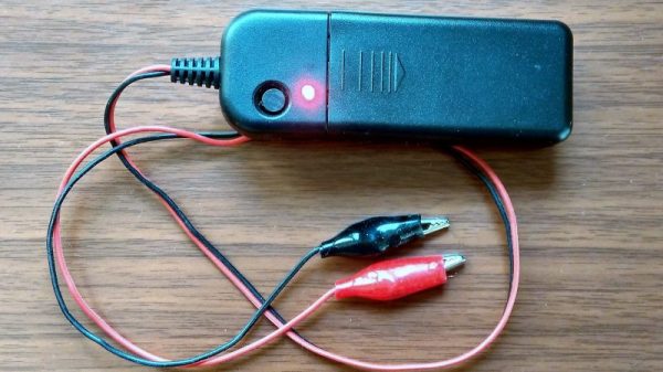
To wrap up the build, he added a 2000mAh 3.7V Li-Ion battery and TP4056 charger, with a DC-DC boost converter to get 5V for the Arduino. Though if you wanted to create a benchtop version of this device, you could delete those components in favor of a 5V AC/DC adapter.
We’ve seen our fair share of DIY function generators, ranging from minimalist builds to hardware that could pass for a commercial offering. We’ve even seen some cheap turn-key function generators, though the usual warnings about getting what you pay for apply.
Continue reading “Arduino Powered Portable Function Generator” →