DUO 128 Elite, 4 Bit CPU

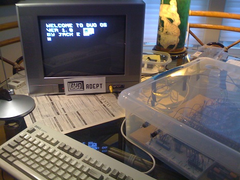
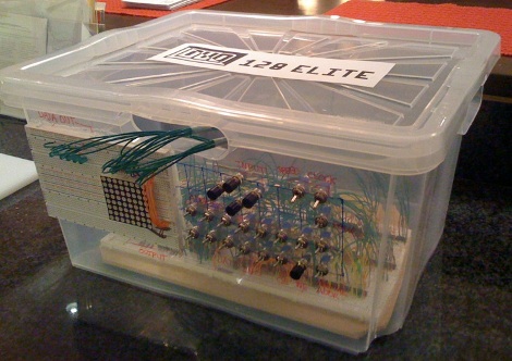
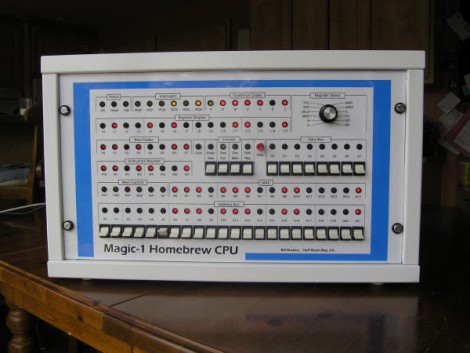
We’re not sure how we missed [Jack Eisenmann’s] 4 bit TTL CPU when we were tipped off the first time, but we’re glad it was sent in again for us to feature it.

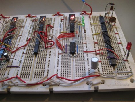
41 different ICs (mostly TTL) come together to comprise the DUO 128 Elite. While the architecture is a little different than what we’ve seen before, using “nyckles”, the DUO 128 Elite still works perfectly. Catch a video of some example programs, including pong, after the divide.

[Thanks Marc G-C]

Continue reading “DUO 128 Elite, 4 Bit CPU”

Pure TTL Based Clock

We’ll just say, [Kenneth] really likes clocks. His most recent is a pure 7400 series TTL based one, ie no microcontroller as seen in the past, here, here, and here. The signal starts out as a typical 32,768 crystal divided down to the necessary 1Hz, which is then divided again appropriately to provide hours and minutes.

As far as TTL clocks go, this is nothing too original; until it comes to his creative button interface. By using a not as sexy as it sounds multivibrator, he can produce a clean square wave instead of the figity signals produced from buttons to advance and set the time. Like always, he also provides us with a thorough breakdown of his clock, after the jump. Continue reading “Pure TTL Based Clock”

Nokia USB Cable Is USB-to-Serial In Disguise

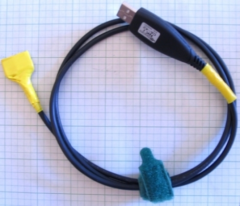
[Jethomson] worked out a way to use a Nokia USB cable at a USB to Serial cable. He was able to pick up one of these cables for less than $3 delivered. A little probing worked out which conductors go with the appropriate signals and from there he developed a way to protect the 3.3v signal levels with a voltage divider.

It’s not surprising that this works, having seen [Will O’Brien’s] post covering serial communications on Nokia phones. In that post we learned that the Nokia phones are using TTL communications. Once you’ve completed [Jethomson’s] modifications to the cable you can follow his examples for using this in conjunction with an Arduino.

Serial Communication With Cell Phones

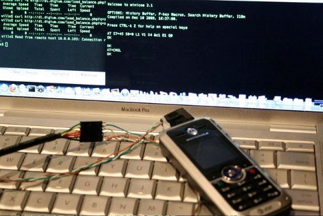
Hackaday alum [Will O’Brien] has been doing some cellphone integration work. He recently picked up some Motorola c168i cellphones from eBay. It turns out there is a serial port that uses TTL communication with a standard head-phone jack as an interface. [Will] soldered up a connector and used a USB to FTDI cable to interface with the phone. To his surprise he was able to read off the stored text messages even though they were PIN protected in the phone’s operating system. The messages on these units were trivial but this is another example of the importance of clearing your data before discarding your devices.

Processor Built With Transistor-Transistor Logic

cpu-built-from-ttl

[Donn] wanted know exactly what is going on inside of a processor so naturally he built a CPU out of TTL components. He had previously built a couple of versions of a computer based on the Z80 processor. Using the troubleshooting skills he learned and a second-hand textbook, he set to work using 74LS series chips connected using the wire-wrap method we’re familiar with from other cpu projects.

The finished product runs well at 1.8 megahertz, but he also included a 2 hertz clock and a step clock for debugging. At the slower speeds, the register board (seen at the left in the picture above) lights LEDs and can be used to tell what the CPU is currently working on. Programming is accomplished through eitherĀ  a dumb terminal or a PC running a terminal emulator.

His writeup is from about five years ago but that didn’t prevent us from getting that fuzzy feeling in the geek-center of our brain when we read about it. It is well written and thorough so if you’re into this kind of thing there’s plenty to enjoy.

[Thanks Raleigh]

Logicport Overview


As promised earlier, the Near Future Laboratory has published an overview of the Logicport Logic Analyzer. They’re using the Playstation 2 analysis as an example. The Logicport uses “interpreters” to define protocols. It has I2C/TWI, SPI, RS232, and CAN 2.0A/2.0B, but you can build your own interpreter based on these. You can specify bit order and the format you want the data in. Slave interpreters can be used for specific tasks: with the PS2 they were used to just show the fifth byte, which is the actual button press.

“Triggers” are used to signal specific activity. On the PS2, one was attached to the falling signal on the slave select line. This event means the master is about to start sending data.

The final area worth exploring is “measurements”. These can be frequency or arbitrary time intervals between events. The Logicport has multiple ground connections to eliminate noise from the signal and you’ll have to play with sample rate and logic level to get things running smooth. It’s nice to see how-tos written from the perspective of someone just getting started with the tool.

SparkFun’s Logic Level Converter


SparkFun has always been good about designing and stocking useful breakout boards. This recently added Logic Level Converter is no exception. It’s uses two BSS138 MOSFETs to shift 5V logic levels to 3.3V. The board handles two separate serial pairs. Just hook up the RX and TX on either side. Provide power at both voltages and the board will happily do the conversion. It’s $2, smaller than the size of a quarter, and perfect for plugging into a breadboard.