Build The Simplest Bipolar Power Supply

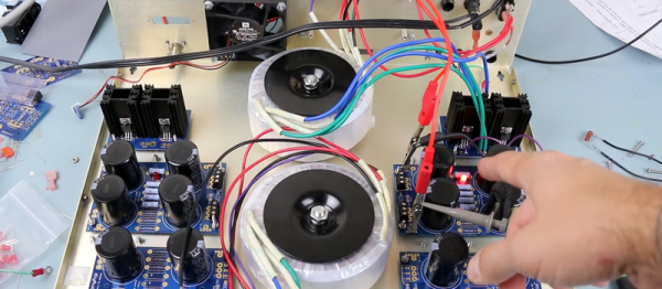
How many integrated circuits do you need to build up a power supply that’ll convert mains AC into a stable DC voltage? Would you believe, none? We just watched this video by [The Current Source] (embedded below), where he builds exactly that. If you’re in the mood for a very well done review of diode bridges as well as half- and full-wave rectifiers, you should check it out.

First off, [TCS] goes through the basics of rectification, and demonstrates very nicely on the oscilloscope how increasing capacitance on the output smooths out the ripple. (Hint: more is better.) And then it’s off to build. The end result is a very simple unregulated power supply — just a diode bridge with some capacitors on the output — but by using really big capacitors he gets down into the few-millivolt range for ripple into a constant load.

The output voltage of this circuit will depend on the average current drawn, but for basically static loads this circuit should work well enough, and the simplicity of just tossing gigantic capacitors at the problem is alluring. (We would toss in a linear regulator somewhere.)

Quibbling over circuit designs isn’t why you’re watching this video, though. It’s because you want to learn something. Check out the rest of his videos as well. [TCS] has only been at it a little while, but it looks like this is going to be a channel to watch.

https://www.youtube.com/watch?v=0iDCsrMM7M0

Two-Stage Tentacle Mechanisms Part III: Putting It All Together

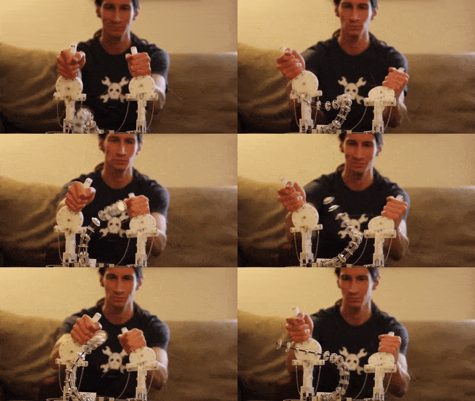
Welcome back to the final chapter in our journey exploring two-stage tentacle mechanisms. This is where we arm you with the tools and techniques to get one of these cretins alive-and-kicking in your livingroom. In this last installment, I’ll guide us through the steps of building our very own tentacle and controller identical to one we’ve been discussing in the last few weeks. As promised, this post comes with a few bonuses:

29323707092_28d8bd1eb8_z
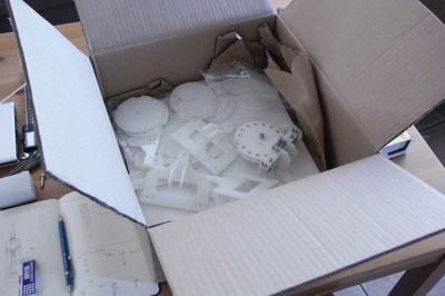
Nothing like a fresh batch o’ parts.

Design Files

  1. The Almighty Bill-o’-Materials
  2. Vector Drawings for laser cutting
    1. DXF files pre-offset (0.003″)
    2. DXF files original
  3. STL Models for 3D Printing
  4. Original Tentacle CAD Model Files
  5. Original Controller CAD Model Files

Depending on your situation, some design files may be more important than others. If you just want to get parts made, odds are good that you can simply cut the pre-offset DXFs from the right plate thicknesses and get rolling. Of course, if you need to tune the files for a laser with a slightly different beam diameter, I’ve included the original DXFs for good measure. For the heavy-hitters, I’ve also included the original files if there’s something about this design that just deserves a tweak or two. Have at it! (And, of course, let us know how you improve it!)

Ok, now that we’ve got the parts on-hand in a pile of pieces,let’s walk through the last-mile tweaks to making this puppet work: assembly and tuning. At this point, we’ve got a collection of parts, some laser-cut, some off the shelf. Now it’s time to string them together.

Continue reading “Two-Stage Tentacle Mechanisms Part III: Putting It All Together”

Creating A PCB In Everything: Friends Don’t Let Friends Use Fritzing

This week, we’re continuing our Creating A PCB In Everything series, where we go through the steps to create a simple, barebones PCB in different EDA suites. We’re done with Eagle, and now it’s time to move onto Fritzing.

fritzing-logoFritzing came out of the Interaction Design Lab at the University of Applied Sciences of Potsdam in 2007 as a project initiated by Professor Reto Wettach, André Knörig and Zach Eveland. It is frequently compared to Processing, Wiring, or Arduino in that it provides an easy way for artists, creatives, or ‘makers’ to dip their toes into the waters of PCB design.
I feel it is necessary to contextualize Fritzing in the space of ‘maker movement’, DIY electronics, and the last decade of Hackaday. Simply by virtue of being an editor for Hackaday, I have seen thousands of homebrew PCBs, and tens of thousands of amateur and hobbyist electronics projects. Despite what the Fritzing’s Wikipedia talk page claims, Fritzing is an important piece of software. The story of the ‘maker movement’ – however ill-defined that phrase is – cannot be told without mentioning Fritzing. It was the inspiration for CircuitLab, and the Fritzing influence can easily be seen in Autodesk’s 123D Circuits.

Just because a piece of software is important doesn’t mean it’s good. I am, perhaps, the world’s leading expert at assessing poorly designed and just plain shitty PCBs. You may scoff at this, but think about it: simply due to my vocation, I look at a lot of PCBs made by amateurs. EE professors, TAs, or Chris Gammell might beat me on volume, but they’re only looking at boards made by students using one tool. I see amateur boards built in every tool, and without exception, the worst are always designed in Fritzing. It should be unacceptable that I can even tell they’re designed in Fritzing.

Fritzing has its place, and that place is building graphical representations for breadboard circuits. Fritzing has no other equal in this respect, and for this purpose, it’s an excellent tool. You can also make a PCB in Fritzing, and here things aren’t as great. I want to do Fritzing for this Creating A PCB In Everything series only to demonstrate how bad PCB design can be.

For the next few thousand words, I am going to combine a tutorial for Fritzing with a review of Fritzing. Fritzing is an important piece of software, if only for being a great way to create graphics of breadboard circuits. As a PCB design tool, it’s lacking; creating parts from scratch is far too hard, and there’s no way to get around the grid snap tool. No one should ever be forced to create a PCB in Fritzing, but it does have its own very limited place.

Continue reading “Creating A PCB In Everything: Friends Don’t Let Friends Use Fritzing”

How To Get Started With The ESP32

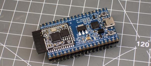
ESP32 is the hottest new wireless chip out there, offering both WiFi and Bluetooth Low Energy radios rolled up with a dual-core 32-bit processor and packed with peripherals of every kind. We got some review sample dev boards, Adafruit and Seeed Studio had them in stock for a while, and AI-Thinker — the company that makes the most popular ESP8266 modules — is starting up full-scale production on October 1st. This means that some of you have the new hotness in your hands right now, and the rest of you aren’t going to have to wait more than a few more weeks.

As we said in our first-look review of the new chip, many things are in a state of flux on the software side, but the basic process of writing, compiling, and flashing code to the chip is going to remain stable. It’s time to start up some tutorials!

Continue reading “How To Get Started With The ESP32”

Creating A PCB In Everything: Eagle DRC And Gerber Files

For the next post in the Creating A PCB series, we’re going to continue our explorations of Eagle. In Part 1,  I went over how to create a part from scratch in Eagle. In Part 2, we used this part to create the small example board from the Introduction.

This time around I’ll be going over Design Rule Check (DRC) — or making sure your board house can actually fabricate what you’ve designed. I’ll also be covering the creation of Gerber files (so you can get the PCB fabbed anywhere you want), and putting real art into the silkscreen and soldermask layers of your boards.

The idea behind this series is to explore different EDA suites and PCB design tools by designing the same circuit in each. You can check out the rest of the posts in this series right here.

Continue reading “Creating A PCB In Everything: Eagle DRC And Gerber Files”

Creating A PCB In Everything: Eagle, Part 2

In the last (and first) post in this series, we took a look at Eagle. Specifically, we learned how to create a custom part in Eagle. Our goal isn’t just to make our own parts in Eagle, we want to make schematics, boards, and eventually solder a few PCBs.

The board we’ll be making, like all of the boards made in this Creating A PCB In Everything series, is the Nanite Wesley, a small USB development platform based on the ATtiny85. This board has less than a dozen parts, most of which are through-hole. This is the simplest PCB I can imagine that has sufficient complexity to demonstrate how to make a board.

With that said, let’s get onto the second part of our Eagle tutorial and lay out our circuit board.

Continue reading “Creating A PCB In Everything: Eagle, Part 2”

Creating A PCB In Everything: Eagle, Part 1

For the first in a series of posts describing how to make a PCB, we’re going with Eagle. Eagle CAD has been around since the days of DOS, and has received numerous updates over the years. Until KiCad started getting good a few years ago, Eagle CAD was the de facto standard PCB design software for hobbyist projects. Sparkfun uses it, Adafruit uses it, and Dangerous Prototypes uses it. The reason for Eagle’s dominance in a market where people don’t want to pay for software is the free, non-commercial and educational licenses. These free licenses give you the ability to build a board big enough and complex enough for 90% of hobbyist projects.

Of course, it should be mentioned that Eagle was recently acquired by Autodesk. The free licenses will remain, and right now, it seems obvious Eagle will become Autodesk’s pro-level circuit and board design software.

Personally, I learned PCB design on Eagle. After a few years, I quickly learned how limited even the professional version of Eagle was. At that point, the only option was to learn KiCad. Now that Eagle is in the hands of Autodesk, and I am very confident Eagle is about to get really, really good, I no longer have the desire to learn KiCad.

With the introduction out of the way, let’s get down to making a PCB in Eagle.

Continue reading “Creating A PCB In Everything: Eagle, Part 1”