There are a great many display technologies available if you wish to make a digital clock. Many hackers seem to have a penchant for the glowier fare from the Eastern side of the Berlin Wall. [ChristineNZ] is one such hacker, and managed to secure some proper Soviet kit for an alarm clock build.
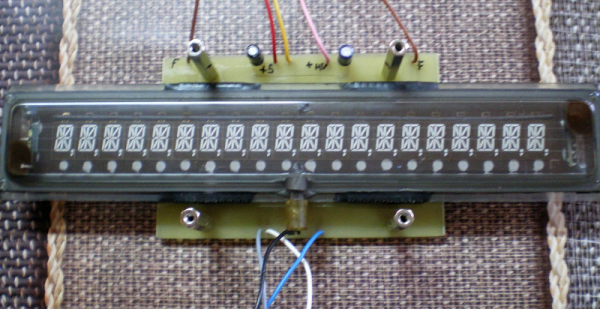
The clock employs an IV-27M vacuum fluorescent display, manufactured in the now-defunct USSR. Featuring 13 seven-segment digits, it’s got that charming blue glow that you just don’t get with other technologies. A MAX6921AWI chip is used to drive the VFD, and an Arduino Mega is the brains of the operation. There’s also an HD44780-compliant LCD that can display further alphanumeric information, and a 4×4 keypad for controlling the device.
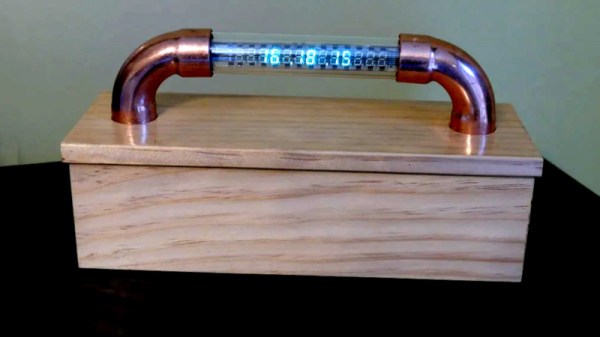
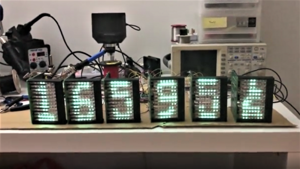
The best part of the build though is the enclosure. The VFD is encased in a glass tube, and supported at either end by 90-degree copper pipe couplers. These hold the VFD aloft, and also act as a conduit for the wires coming off each end of the tube. It’s all built on top of a wooden base that holds the rest of the electronics.
It’s an attractive build, and we love the floating look created by the glass tube construction. It’s not the first time we’ve seen old Russian VFDs, and we doubt it will be the last. Video after the break.

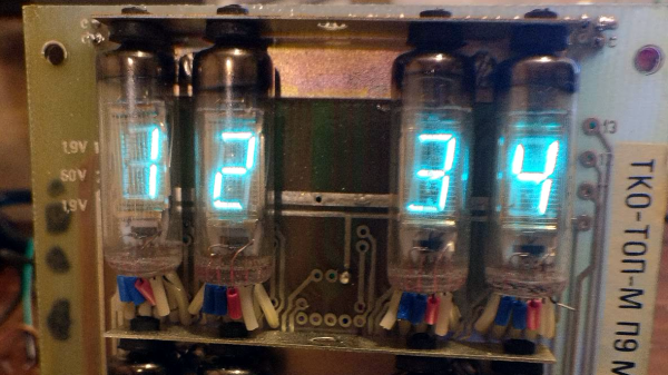
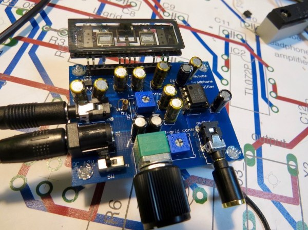
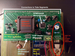 After getting the VFDs lighting up and figuring out the circuitry on the back, [InThePartsBin] decided that a clock was the best thing to build out of it. It was decided that a specialized VFD driver chip was the easiest way to make the thing work, so a MAX6934 was ordered. To give the clock some brains, an ATmega328 was recruited and to keep time, [InThePartsBin] had some DS3231 real-time clock modules left over from a previous project, so they were recruited as well. A daughterboard was designed to sit on the back of the vintage board and hold the ‘328 and the VFD driver chip.