Visualizing Verilog Simulation

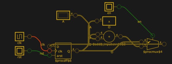
You don’t usually think of simulating Verilog code — usually for an FPGA — as a visual process. You write a test script colloquially known as a test bench and run your simulation. You might get some printed information or you might get a graphical result by dumping a waveform, but you don’t usually see the circuit. A new site combines Yosys and a Javascript-based logic simulator to let you visualize and simulate Verilog in your browser. It is a work in progress on GitHub, so you might find a few hiccups like we did, but it is still an impressive piece of work.

Continue reading “Visualizing Verilog Simulation”

Learn FPGA With This Persistence Of Vision Hack

Everybody wants to give FPGA development a try and here’s a great way to get into it. You can build your own Persistence of Vision display using a $30 dev board. It’s a fun project, and you’ll learn quite a bit about designing for an FPGA, as well as using the Quartus design software.

The inspiration for this article comes from [vpecanins] who did an example project where you wave the board back and forth and a message appears in mid air. This uses the MAX1000, a pretty powerful yet odd FPGA board for about $30. It contains an Intel MAX10 (when did Intel start making FPGAs? Remember, Intel bought Alterra back in 2015). I find the board odd because it also holds an accelerometer that you can talk to using SPI. That’s a little strange for a generic FPGA board, but paired with eight on-board LEDs it’s perfect for this demo.

Since I didn’t find any written documentation for this example, I thought we’d help out and take you on a step-by-step tour of the project. What’s more, in a future installment, I’ll show you how to make some significant changes to the tutorial that will make it even more practical as a base for other projects.

Continue reading “Learn FPGA With This Persistence Of Vision Hack”

Getting Good At FPGAs: Real World Pipelining

Parallelism is your friend when working with FPGAs. In fact, it’s often the biggest benefit of choosing an FPGA. The dragons hiding in programmable logic usually involve timing — chaining together numerous logic gates certainly affects clock timing. Earlier, I looked at how to split up logic to take better advantage of parallelism inside an FPGA. Now I’m going to walk through a practical example by modeling some functions. Using Verilog with some fake delays we can show how it all works. You should follow along with a Verilog simulator, I’m using EDAPlayground which runs in your browser. The code for this entire article is been pre-loaded into the simulator.

If you’re used to C syntax, chances are good you’ll be able to read simple Verilog. If you already use Verilog mostly for synthesis, you may not be familiar with using it to model delays. That’s important here because the delay through gates is what motivates us to break up a lot of gates into a pipeline to start with. You use delays in test benches, but in that context they mostly just cause the simulator to pause a bit before introducing more stimulus. So it makes sense to start with a bit of background on delays.

Continue reading “Getting Good At FPGAs: Real World Pipelining”

Pipelining Digital Logic In FPGAs

When you first learn about digital logic, it probably seems like it is easy. You learn about AND and OR gates and figure that’s not very hard. However, going from a few basic gates to something like a CPU or another complex system is a whole different story. It is like going from “Hello World!” to writing an operating system. There’s a lot to understand before you can make that leap. In this set of articles, I want to talk about a way to organize more complex FPGA designs like CPUs using a technique called pipelining.

These days a complex digital logic system is likely to be on an FPGA. And part of the reason we can get fooled into thinking digital is simple is because of the modern FPGA tools. They hide a lot of complexity from you, which is great until they can’t do what you want and then you are stuck. A good example of that is where you are trying to hit a certain clock frequency. If you aren’t careful, you’ll get a complaint from the tool that you can’t meet timing constraints.

Continue reading “Pipelining Digital Logic In FPGAs”

Forth System-On-Chip Takes Us Back To The 80s

For anyone who has dealt with the programming language Forth, odds are good that you picked it up back in the 80s. Since the language is still in use for many applications, though, you might not have this sort of nostalgic feeling for the language that some might have. For that, though, you might want to try out [Richard]’s implementation which simulates the microcomputers of the 80s using this unique language.

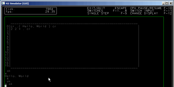
The system has an FPGA-based CPU written in Verilog. It runs on a Nexys-3 board and features PS/2 Keyboard input, a VGA output with a VHDL VT100 terminal emulation module, access to the Flash and onboard SRAM, and a UART. With all of that put together it’s virtually a Forth-based time machine. It’s also extremely well documented even if you’re just curious how it works and aren’t planning on building your own.

The project also includes a CPU simulator written in C which can model the entire computer if you don’t have the hardware for building the actual computer. [Richard] also released everything that you’d need to roll out your own Forth computer on the GitHub page. There are other ways of heading way back to the 1980s, though, like using the quirky Parralax Propeller.

Learn FPGA Programming From The 1940s

We often think that not enough people are building things with FPGAs. We also love the retrotechtacular posts on old computer hardware. So it was hard to pass up [karlwoodward’s] post about the Chip Hack EDSAC Challenge — part of the 2017 Wuthering Bytes festival.

You might recognize EDSAC as what was arguably the first operational computer if you define a computer as what we think of today as a computer. [Maurice Wilkes] and his team invented a lot of things we take for granted today including subroutines (Wheeler jumps named after a graduate student).

The point to the EDSAC challenge was to expose people to creating designs with FPGAs, particularly using the Verilog hardware description language (HDL). If you want to follow along or run your own Chip Hack, the materials are available on the Web. You can see an FPGA driving a tape punch to create souvenir tapes in the video, below.

Some of the exercises are pretty simple and that’s perfect if you are starting out. The challenge uses a board with a Lattice ice40 FPGA and the open source toolchain for Lattice we’ve covered before. In fact, we’ve even done our own tutorials on the same basic device (but not the same board). Our final project generated PWM, not paper tape.

For the record, EDSAC was awesome. The execution unit was serial and processed bits that marched in one at a time over a mercury delay line. There is quite a bit of documentation and even some simulators, so if you ever wanted to get your hands into an old computer, this one isn’t a bad one to try.

Continue reading “Learn FPGA Programming From The 1940s”

FPGA Clocks For Software Developers (or Anyone)

It used to be that designing hardware required schematics and designing software required code. Sure, a lot of people could jump back and forth, but it was clearly a different discipline. Today, a lot of substantial digital design occurs using a hardware description language (HDL) like Verilog or VHDL. These look like software, but as we’ve pointed out many times, it isn’t really the same. [Zipcpu] has a really clear blog post that explains how it is different and why.

[Zipcpu] notes something we’ve seen all too often on the web. Some neophytes will write sequential code using Verilog or VHDL as if it was a conventional programming language. Code like that may even simulate. However, the resulting hardware will — at best — be very inefficient and at worst will not even work.

Continue reading “FPGA Clocks For Software Developers (or Anyone)”