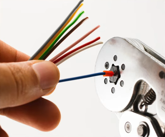
These Wire Strippers Are Made From PCBs

The rise in cheap PCB fabrication has made old-school prototyping methods such as wire wrapping somewhat passé, but it still has its place. And if you’re going to wire wrap, you’re going to want a quick and easy way to strip that fine Kynar-insulated wire. So why not use PCB material to make this handy wire-wrapping wire stripper?

The tool that [danielrp] built is pretty simple – just a pair of razor blades held together so as to form a narrow slot to cut insulation while leaving the conductor untouched. The body of the tool is formed of two PCBs, between which the blades are sandwiched. [danielrp] designed the outline of the PCBs in DraftSight, then exported a DXF into EAGLE to make the Gerbers. The fabricated boards needed a little post-processing, including tapping the holes on one side to accept the screws that hold the tool together. We were surprised that FR4 took the threads at all, but it seems to work for this low-torque application. The disposable snap-type blades were sandwiched between the PCBs and the gap between them adjusted for nick-free stripping. The video below shows the design and build process.

We always appreciate homemade tools, and the fact that you can get a stack of PCBs for almost nothing makes us wonder what else we could use them for. We recently saw them used in a unique word clock, and even turned into a folding circuit sculpture.

Continue reading “These Wire Strippers Are Made From PCBs”

Making Your Breadboard Projects A Little More Permanent

Many a budding electronics maker got their start not with a soldering iron, but with the humble breadboard. With its push connections, the breadboard enables electronics experimentation without requiring the specialised skill of soldering or any dangerous hot tools. What it lacks is a certain robustness that can make all but the simplest projects rather difficult to execute. [Runtime Micro] have shared a few tips on making things just a little more robust, however.

Applied correctly, these techniques have the added bonus of making a project neat, tidy, and easy to troubleshoot.

The fundamental principle behind this process is replacing point-to-point jumper wires with custom cables, made using 0.1″ pitch headers and wire-wrapping techniques. Other techniques include pinning down components with Blu-tack, and selecting components with the appropriate wire diameter to avoid them falling out of the breadboard’s spring clip contacts. There are also useful tips on using foam tape for appropriate strain relief.

While breadboards aren’t really suitable for projects dealing with high frequencies and can rapidly become unmanageable, these basic techniques should improve a project’s chance of success. These simple ways of improving connection quality and reducing the likelihood of things falling apart are likely to reduce frustration immensely.

However, once a maker has a taste for corralling electrons to do their bidding, soldering should be the first lesson on the agenda.

[Thanks to stockvu for the tip!]

String Art Robot Is An Autorouter In Reverse

In the depths of Etsy and Pinterest is a fascinating, if tedious, artform. String art, the process of nailing pins in a board and wrapping thread around the perimeter to create shapes and shading, The most popular project in this vein is something like putting the outline of a heart, in string, in the shape of your home state. Something like that, at least.

While this artform involves about as much effort as pallet wood furniture, there is an interesting computational aspect of it: you can create images with string art, and doing this is a very, very hard problem to solve with an algorithm. Researchers at TU Wien have brought out the best that string art has to offer. They’ve programmed an industrial robot to create portraits out of string.

The experimental setup for this is about as simple as it gets. It’s a circular frame studded with 256 hooks around the perimeter. An industrial robot arm takes a few kilometers of thread winds a piece of string around one of these hooks, then travels to another hook. Repeat that thousands and thousands of times, and you get a portrait of Ada Lovelace or Albert Einstein.

The wire wrapped backplane of a DEC PDP-11. This was assembled by a robot that was programmed with an autorouter. It’s also string art.

The real trick here is the algorithm that takes an image and translates it into the paths the string will take. This is an NP-hard problem, but it is a surprisingly well-studied problem. The first autorouters — the things you should never trust to route traces between the packages on your PCB — we created for wire wrapped computers. Here, computers would find the shortest path between whatever pins had to be connected together. There were, of course, limitations: pins could only have so many connections on them thanks to the nature of wire wrapping, and you couldn’t have one gigantic mass of wires for a parallel bus. The first autorouters were string art algorithms, only in reverse.

You can take a look at the complete publication here.

You’ll also find prior art (tee-hee) in our own pages. Here is an artist doing it by hand, and here’s a machine to do it for you if you’re lazy. We’ve even seen further work on the underlying algorithm on Hackaday.io.

Ask Hackaday: Whatever Happened To Wire Wrapping?

Back in the 70s when I started getting interested in electronics, tons of magazines catered to the hobbyist market. Popular Electronics was my favorite, and I think I remember the advertisements more than anything, probably because they outnumbered articles by a large margin. Looking back, it seemed like a lot of ad space was sold to companies hawking the tools and materials needed for wire wrapping, which was very popular for prototyping in the days before solderless breadboards were readily available. I remember beauty shots of neat rows of small, gold posts, with stripped wires wrapped evenly around them.

To the budding hobbyist, wire wrapping looked like the skill to have. With a huge selection of posts, terminals, and sockets for ICs and discrete components, as well as a wide range of manual and powered wrapping tools, it seemed like you could build anything with wire wrapping. But fast forward just a decade or so, and wire wrapping seemed to drop out of favor. And today — well, does anyone even wire wrap anymore?

Continue reading “Ask Hackaday: Whatever Happened To Wire Wrapping?”

Hackaday Video: Wire Wrap 101 with Bil Herd

Wire Wrap 101

You might notice that many of my writings start with “Back in the day”. Not wanting to disappoint I will say that back in the day we used to use wire wrap technology when we needed a somewhat solid, somewhat reliably assembly. Given a readable schematic a good tech could return a working or near-working unit in a day or two depending on the completeness and accuracy of the schematic.

wire-wrap2

Properly done a wire wrap assembly is capable of fairly high speed and acceptable noise when the alternative option of creating a custom PCB would take too long or not allow enough experimentation.  Wire wrap is also used in several types of production, from telco to NASA, but I am all about the engineer’s point of view on this.

My first wire wrap tool and wire wrap wire came from Radio Shack in the mid 1970’s.  I still have the wire, because frankly its kind of cheap wire and I use it when it’s the only thing I can reach quickly when I need to make a jumper on a PCB. The tool is still around also, given the fact that I can’t find it at the moment the one shown here is my new wire wrap tool which is good for low quantity wrapping, unwrapping and stripping.

ww-tool2The skinny little wrap tool is okay for hobbyist as the wraps are fine with a little practice.  But I do recommend investing in high-quality wire.  A common wire available is Kynar® coated, a fluorinated vinyl that performs well as an insulator.

Before I go too much further, here’s the video walkthrough of wire wrap, its uses, and several demonstration. But make sure you also join me after the break where I cover the rest of the information you need to start on the road to wire wrap master.

Continue reading “Wire Wrap 101”

“Zero Overhead” Z80 Computer Focuses On Performance

z80_wirewrap_computer_zero_overhead

There’s something quite satisfying about building your own computer. Nowadays, constructing your own desktop PC is relatively easy, so if you really want to get your hands dirty, you have to take a step back in time and give some vintage hardware a spin.

[YT2095] has spent a good portion of the last two months building a computer based on the classic Z80 CPU. His machine, called “Z Eighty Development” or “ZED” for short is an amazing build, and most definitely a labor of love. He has put an estimated 700+ hours into this machine and it’s a beaut! When closed, the machine is pretty unassuming, but once he folds down the keypad, you can see that all of his time has been put to good use.

Most of the board’s components are connected together via wire wrap, including the large 48k memory card he built, as you can see from the link above. The wide array of add on cards all work together to accomplish his goal of “zero overhead” – freeing up the Z80 from having to do any unnecessary processing, such as I/O, etc.

It’s quite an impressive build, and ranks up there with some of the best Z80 based computers we have seen through the years.

Electromechanical Computer Built From Relays

This is Zusie, a computer built out of electromechanical relays. [Fredrik Andersson] picked up a lot of about 100 telephone exchange circuit boards, each with about 16 relays on them. After getting to know a heat gun really well he ended up with 1500 working relays with which to play. The machine runs slowly, it iss noisy, but it definitely works. After the break you can see it running and assembly code program that he wrote.

The instruction set is based on boards running microcode. These store the operational commands for each instruction the processor has available to it and they run in parallel with the rest of the operations.

We’re always surprised to see that these home-built processors work. Mostly because of the complexity involved in assembling them. How hard is it to find a shorting connection or a malfunctioning relay? Those problems aren’t limited to this application either, what do you do if a transistor-logic CPU has a malfunctioning chip?

Continue reading “Electromechanical Computer Built From Relays”