It isn’t unusual to expect a precisely regulated voltage in an electronic project, but what about times when you need a precise current? Over on EDN, prolific [Stephen Woodward] explains how to use a precision Zener diode to get good results. [Stephen] takes you through the math for two topologies and another circuit that uses a pair of bipolar transistors.
You might wonder why you need a precise current source or sink. While it is nice to drive things like LEDs with a constant current, you probably don’t need ultra-precise currents. However, charging a capacitor with a constant current produces a very nice linear voltage ramp. When you use a resistor to bias collector current in a bipolar amplifier, you are just poorly imitating a constant current source, too. That’s just two of many examples.
Normally, when you want a low DC voltage from the AC line, you think about using a transformer of some kind. [RCD66] noticed that an AC monitor meter must have some sort of power supply but had no transformers in sight. That led to an exploration of how those work and how you can use them, too. You can watch the work in the video below.
Sensibly, there is a transformer in the test setup — an isolation transformer to make it safe to probe the circuit. But there’s no transformer providing voltage changes. Isolation is important even if you are taking apart something commercial that might be trasformerless.
The circuit is simple enough: it uses a capacitor, a resistor, and a pair of diodes (one of them a zener diode). He uses this basic circuit to drive simple regulators with input and output filter capacitors. We’ve seen many variations on this design over the years.
You can’t draw a lot of power through this arrangement. But sometimes it is all you need. However, this is pretty dangerous, as we’ve discussed before. Be sure you understand exactly what the risks are before you decide to build something like this.
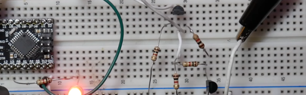
Whether it’s a game of D&D or encrypting top-secret information, a wide array of methods are available for generating the needed random numbers with high enough entropy for their use case. For a tabletop game this might be a single die but for more sensitive applications a more robust method of generating random numbers is needed. Programmers might reach for a rand() function of some sort, but these pseudorandom numbers don’t cut the mustard for encryption. For that you’ll need a true random number generator (RNG), and this open-source hardware RNG uses one of the better methods we’ve seen.
The device, called RAVA, is based on a property found in many electronic devices called avalanche breakdown. Avalanche breakdown occurs when a high voltage (in this case approximately 25V) is applied in the reverse bias direction, with this device using a pair of Zener diodes. When this high voltage is applied, an “avalanche” of electrons occurs which allows the diodes conduct in the opposite direction that they would when they are forward biased. This isn’t a constant current flow, though; there are slight variations over time which can be amplified and used as the random number generator. The noise is amplified over a series of op amps and then fed to an ATmega32U4 microcontroller which can provide the user with 136.0 Kbit/s of random data.
Unlike other random number generators, this device is based on a method generally accepted to be truly random. Not only that, but since it’s based on discrete hardware it can be accessed directly for monitoring and replacement in case of faults, unlike other methods which are more “black boxes” and are more opaque in their processes which are thus harder to audit. We also appreciate it’s open-source nature as well, and for some more information on it be sure to check out the paper on it in IEEE. If you’re looking for something to generate random numbers but will also bring some extra flair to the next game night, take a look at this radioactive dice replacement.
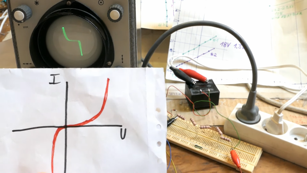
To a lot of us, curve tracing seems to be one of those black magic things that only the true wizards understand. But as [DiodeGoneWild] explains, curve tracing really isn’t all that complicated, and it doesn’t even require specialized test instruments — just a transformer, a couple of resistors, and pretty much whatever oscilloscope you can lay your hands on.
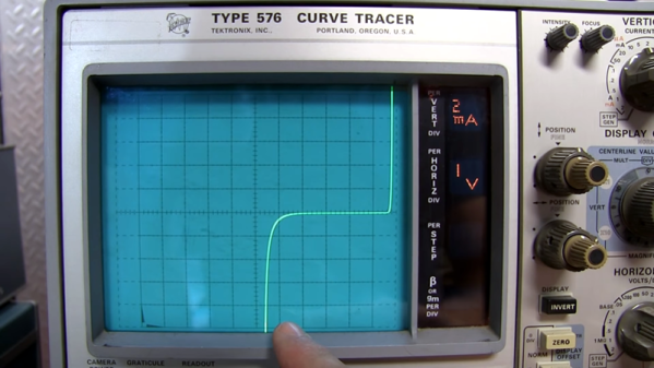
True to his handle, [DiodeGoneWild] concentrates on the current-voltage curves of Zener diodes in the video below, mainly as a follow-up to his recent simple linear power supply project, where he took a careful look at thermal drift to select the best Zener for the job. His curve tracer is super simple — just the device under test in series with a bunch of 10-ohm resistors and the secondary winding of a 12-volt transformer. The probes of his oscilloscope — a no-frills analog model — go across the DUT and the resistor, and with the scope in X-Y mode, the familiar current-voltage curve appears. Sure, the trace is reversed, but it still provides a good visualization of what’s going on. The technique also works on digital scopes; just be ready for a lot of twiddling to get into X-Y mode and to get the trace aligned.
Of course it’s not just diodes that can be tested with a curve tracer, and [DiodeGoneWild] showed a bunch of other two-lead components on his setup. But for our money, the neatest trick here was using a shorted bridge rectifier to generate a bright spot on the curve to mark the zero crossing point. Clever indeed, and pretty useful on a scope with no graticule.
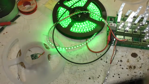
While addressable LED strips are all the rage, [Mike] from [mikeselectricstuff] has been working on an installation using the more basic two-wire strips that are simply controlled via PWM dimming. He’s recently figured out a tidy way to send sensor signals down these strips without adding any additional cabling.
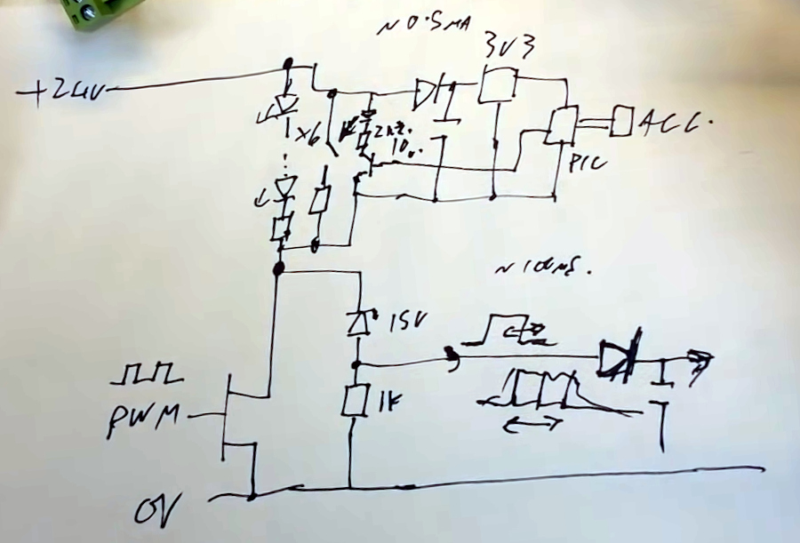
The circuit in question.
The build uses 24 V LED tape, which consists of gangs of 6 LEDs in series with a forward voltage of 3V. Thus, these strips don’t even begin to light until approximately 18V is across them.
By adding a 15 V Zener diode and a resistor across the MOSFET which dims the LEDs, a voltage of around 9 V can be put across the LEDs without lighting them up when the MOSFET PWM dimmer is in its off phase. A PIC10F322 microcontroller and an accelerometer can then be run from this voltage, with the aid of a 3.3 V regulator wired in parallel with the LEDs. The regulator must also be able to handle the full 24 V when the LEDs are switched on.
A transistor is also wired up, switching a 2.2 K resistor in parallel with the LEDs. When turned on by the PIC, this transistor causes roughly a 10 mA current to flow through the Zener diode and its series resistor. The voltage developed across that series resistor can be measured as the transistor is turned on and off. In this case, the pulse width used to turn that transistor on is relative to motion detected by the accelerometer on the end of the LED strip.
Turning the LEDs on at 100% duty cycle prevents the system working, as the pulse widths generated by the sensor circuit can’t be detected when the LED line is held high all the time. However, in practice, it matters not — running the LEDs at a maximum 98% duty cycle eliminates the issue.
It’s an ingenious way to send sensor signals down a two-wire LED strip, even if it does take a second to wrap one’s head around it. It also seems to do a great job of adding motion-reactive effects to the LED strips in question. It’s not the first LED project we’ve seen from [Mike], either. Video after the break.
We always enjoy [w2aew’s] videos, and his latest on zener diodes is no exception. In it, he asserts that all Zener diodes are not created equal. Why? You’ll have to watch the video below to find out.
Zener diodes are one of those strange items that have several uses but are not as popular as they once were. There was a time when the Zener was a reasonable way to regulate a voltage inexpensively and easily. Unfortunately the regulation characteristics were not very good, and the power lost was very high. But that was sometimes a reasonable trade, compared to putting a pass transistor and the associated discrete circuitry in place to make a linear regulator. With the advent of chips like the 7800-series regulators, you can have a high-quality regulator with one extra wire and still keep your costs under $1. Even if you want to do better and go with a switching power supply, that’s easy now and not much more expensive.
[Kevin Darrah] wanted to make a simple 3.3V regulator without using an integrated circuit. He wound up using two common NPN transistors and 4 1K resistors. The circuit isn’t going to beat out a cheap linear regulator IC, but for the low component count, it is actually pretty good.
In all fairness, though, [Kevin] may have two transistors, but he’s only using one of them as a proper transistor. That one is a conventional pass regulator like you might find in any regulator circuit. The other transistor only has two connections. The design reverse biases the base-emitter junction which results in a roughly 8V breakdown voltage. Essentially, this transistor is being used as a poor-quality Zener diode.